


Operating Instructions
30
Before the instrument is turned on, all protective earth terminals, extension cords, and devices
connected to the power supply should be connected to a protective earth ground. Any interruption of the
protective earth grounding will cause a potential shock hazard that could result in personal injury.
This instrument can be damaged by electrostatic discharge into the GP-IB and control connectors, or the
switches on the rear panel
while the unit is turned on. Do not cause an electrostatic discharge into these
connectors and switches (which may occur when they are touched) while the unit is turned on.
Also, consistent with good engineering practice, leads attached to customer accessible signal/monitoring
ports should be twisted and shielded to maintain the instruments specified performance.
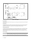
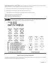
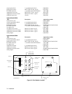
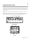
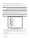
Controls and Indicators
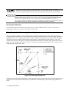
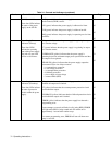
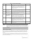
The front-panel controls and indicators are shown in Figure 3-1 and described in Table 3-1. Table 3-1 also lists the
paragraphs, in which, use of the controls and indicators is described.
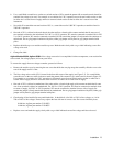
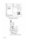
Output Range For An Autoranging Power Supply
The power supply can operate as a constant voltage (CV) or constant current (CC) source over a wide range of output
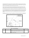
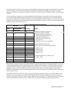
voltage and current combinations. The specifications table contains a graph showing the overall output range of the power
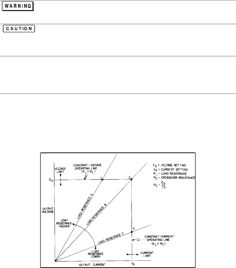
supply. Figure 3-2 shows a rectangular operating locus that is defined by voltage and current settings of the power supply.
The point on that locus at which the power supply actually operates is determined by the load resistance. Three load-
resistance lines are shown on Figure 3-2. The line representing load resistance A, the highest load resistance shown on the
graph, crosses the operating locus at point 1. Point 1 is on the part of the operating locus defined by the voltage setting, so
the power supply operates in CV mode.
Figure 3-2. Determining Operating Point
Similarly, the line representing load resistance C, the lowest load resistance shown on the graph, crosses the operating locus
at point 3. Point 3 is on the part of the operating locus defined by the current setting, so the power supply operates in CC
mode.