


Operating Instructions
60
completed with the first. Therefore, sending device trigger after sending a command assures that the second instrument
cannot begin to receive commands until the first instrument has processed its commands.
For example, assume the following commands are sent to four power supplies assigned to addresses called PS1, PS2, PS3,
and PS4:
OUTPUT PS1; "HOLD ON’’ 5A’’
OUTPUT PS2; "HOLD ON; lA"
TRIGGER PS1
TRIGGER PS2
OUTPUT PS3; "HOLD OFF; 10A"
TRIGGER PS3
OUTPUT PS4; "HOLD OFF. 2A"
Power supply 2 will start to change only after power supply 1 has started to change, and power supply 4 will start to change
only after power supply 3 has started to change. Note that this feature concerns only the processing of the GP-IB command.
The time required for the power supplies to settle at their new values depends on the load and on the direction and amount
of change.
Store/Recall. The power supply can store up to 16 complete power supply states except for output on/off. This allows the
operator to preset frequently used values, which can then be recalled when needed with a single command. Preset values are
stored and recalled using these codes (3 and 1 used as examples):
STO 3
RCL 11
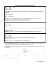
Sending a store command causes a "snapshot" of the present machine state to be stored. The power supply can then be
programmed with new values. Note that only those values to be changed need be reprogrammed. For example, if the
following command strings were sent in listed order to the power supply, the string stored in register 1 would include a
current setting of 2 A and CC foldback in
addition to a voltage setting of 6 V. The string stored in register 2 would include a voltage setting of 8 V in addition to a
current setting of 5 A and CV foldback. Note that the stored because the output was turned off. The store/recall designators
need not be assigned in consecutive order, but they must be in the range of 0 to 15.
OUT OFF
VSET 5V; ISET 2A; FOLD CC; STO 0
VSET 8V; STO 1
ISET 5A; FOLD CV; STO 2
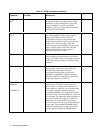
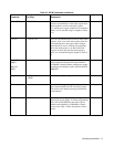
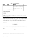
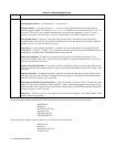
Status Register. The power supply maintains an 9-bit status register that reflects the present state of the unit. Each of the
nine bits represents a separate condition; when the condition is true the corresponding bit is 1. Bits are assigned as shown in
Table 3-9.
The status register can be read by sending:
STS?
and addressing the power supply to talk. The response from the power supply is in this format:
STS xxx
where xxx is a string of ASCII decimal digits. These digits specify an integer which is equal to the sum of the bit weights of
the true conditions.