


Operating Instructions
35
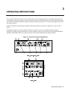
d. Turn OUTPUT ADJUST knob clockwise, press DISPLAY SETTINGS switch, and check that AMPS setting has
increased. CV indicator should be on and CC indicator should be off.
e. Press momentary-contact OUTPUT ADJUST pushbutton switch once; VOLTAGE indicator should turn on and
CURRENT indicator should turn off.
f. Turn OUTPUT ADJUST knob clockwise and check that output voltage increases from zero to full output voltage as
indicated on VOLTS display. Continued clockwise rotation may cause VOLTS display to indicate + OL, and ERROR
indicator will light (turns off one second after clockwise rotation stops).
g. Check overvoltage protection circuit by turning OVP ADJUST control counterclockwise until OVP circuit trips. Output
should drop to 0 V, CV indicator turns off, and DISABLED and OV indicators turn on (SRQ and VOLTAGE
indicators remain on).
h. Reset OVP circuit by turning OVP ADJUST control fully clockwise and turning unit off and back on. Output voltage
should come on at 0 volts.
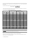
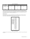
i. To check constant current circuit, turn power supply off and short rear panel + and - output terminals with a wire of
sufficient gauge to carry the supply’s maximum current output (see Table 3-3).
j. Turn power supply on and press OUTPUT ADJUST switch once to turn on VOLTAGE indicator. Turn OUTPUT
ADJUST knob clockwise, press DISPLAY SETTINGS switch, and check that VOLTS setting has increased. CC
indicator should be on and CV indicator should be off.
k. Press OUTPUT ADJUST switch once; CURRENT indicator should turn on and VOLTAGE indicator should turn off.
1. Turn OUTPUT ADJUST knob clockwise and check that output current increases from zero to full output current as
indicated on AMPS display. Continued clockwise rotation may cause AMPS display to indicate + OL, and ERROR
indicator will light (turns off one second after clockwise rotation stops).
m. Turn off power supply, remove short from output, and read following instructions before connecting load to supply.
Initial Setup and Interconnections
Turn off input ac power before changing any rear-panel connection and make certain all wires and
straps are properly connected and terminal block screws are securely tightened before reapplying
power. Be certain to replace both terminal block covers before reapplying power to avoid exposing
hazardous voltage.
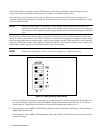
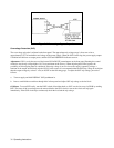
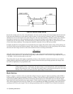
Connecting the Load
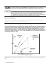
Load connections to the power supply are made at the + and - terminals on the rear panel. Two factors must be considered
when selecting wire size for load connections, conductor temperature and voltage drop.
To satisfy safety requirements, the wires to the load should be at least heavy enough not to overheat while carrying the
power supply output current that would flow if the load were shorted. Use Tables 3-2 and 3-3 to determine the proper wire
gauge for load connections to the power supply.
The wires must be properly terminated with connectors securely attached. Do not connect unterminated wires to the power
supply.
The minimum wire size required to prevent overheating will not usually be large enough to provide good voltage regulation
at the load. For proper regulation the load wires should be large enough to limit the voltage drop to no more than 0.5 volts