


Operating Instructions
65
When the power supply is addressed to talk after and addressing the power supply to talk. The response from TEST? has
been received, it responds in this format: the power supply will be either:
TEST x
where x is a decimal number from 0 to 22. See the Service Manual for a listing of the selftest failure
codes. TEST 0 indicates that all tests passed.
The test command does not complete until the power supply control circuits have had time to settle. This prevents
perturbations on the power supply output. The test command takes about 500 ms to execute.
Note that the test command in no way changes the supply can be remotely programmed state or the output of the power
supply
Model Identification. The power supply model number can be determined from the controller by sending the command:
ID?
and addressing the power supply to talk. The response from the power supply will be either:
ID Agilent 603xA or ID Agilent 603xA, OPT100
with the option 100 identification indicating that the power supply has a reduced output-power capability.
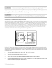
Analog Programming
The output voltage and/or current of the power supply can be remotely programmed by an external resistance or voltage.
The power supply is configured for analog programming with rear-panel slide switches: the analog programming signals are
connected to rear-panel screw-on terminals. Both voltage and current programming can be done at the same time.
The common terminal ( P) is internally connected to the minus (-) output terminal.
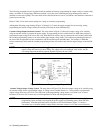
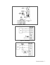
For resistance programming, internal CV and CC current sources supply 1.25 mA currents through the programming
resistors to create programming voltages for the power supply. Resistances of 0 to 4 kilohms program the output from 0 to
full scale. A variable resistor can control the output over its entire range. Or, a variable resistor connected in series and/or
parallel with a fixed resistor can have its control restricted to a limited portion of the output range. Alternatively, a switch
can be used to select fixed values of programming resistance to obtain a set of discrete voltages or currents.
NOTE The switching configuration used may require make before-break contacts to avoid producing the output
voltage transients caused by momentarily opening the programming terminals.
To maintain the temperature and stability specifications of the power supply, any resistors used for programming must be
stable, low-noise resistors with a temperature coefficient of less than 25ppm per °C and a power rating of at least 1/2 watt.
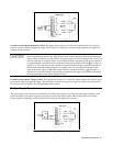
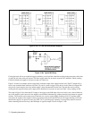
Both voltage and current outputs can also be controlled by a voltage source. A voltage of 0 to 5 volts programs the output
from zero to full scale. Voltage sources of more than 5 volts can be scaled down to the proper range.
Setting the power supply for analog programming of voltage and/or current disables digital programming (front-panel or
GP-IB) for that parameter.