


Programming the Agilent 603xA Power Supplies Using Basic
121
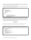
Condition
•
RQS ERR RDY
••
PON FAU
Bit position
76543210
Bit Weight
128 64 32 16 8 4 2 1
Where
•
- Not Used
FAU - Fault Condition
PON - Power on Reset
RDY - Ready to Process Commands
ERR - Programming Error
RQS - Requesting Service
The ERR bit is set when a remote programming error is detected and is cleared when the "ERR?" device command is
received. (See the section on detecting programming errors.)
The FAU bit is the logical OR of all the bits in the fault register. It is cleared when the "FAULT?" device command is
received. (Provided the remote inhibit (INH) line is false).
The FAU bit can thus be used in conjunction with the fault and mask registers to give the programmer a rapid indication that
a user-defined fault has occurred.
The RDY bit is cleared when the Agilent603XA is busy processing commands and set when the processing is completed.
The PON bit is set when power is first applied to the power supply and is cleared upon receipt of the "CLR" device
command or the device clear interface management command.
RQS indicates that the supply has requested service. A serial poll will clear this bit.
The power supply can be serial polled by assigning the serial poll response to a variable:
SPOLL_RESP= SPOLL (@PS)
EXAMPLE 6: Use of serial poll to determine whether the supply passed through or into overrange mode. This
program differs from the previous example only in the method of reading status. Serial poll is useful because it can be
performed within a program line and is much faster than reading a status register. The greater speed is balanced by
the level of status information available. If the user does not want to use interrupts from the power supply serial poll
can provide the same information with periodic checking.
10 ASSIGN @Ps TO 705
20 OUTPUT @Ps;"CLR;UNMASK OR’’
30 !
40 !
50 ! D0 PROGRAM
60 !
70 !
80 IF BIT (SPOLL(@Ps),0) THEN
90 PRINT "SUPPLY ENTERED OR MODE"
100 END IF
110 END
Explanation:
10: Assign I/O path name to power supply
20: Initialize power supply, set ’OR’ bit in mask register
80-100: Conduct serial poll, compare to OR bit if both true, print message
Note: Fault register must be cleared with "FAULT?" query