


Basic Hardware and Function
295
10. Troubleshooting
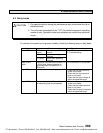
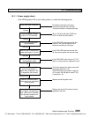
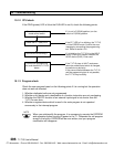
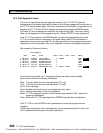
10.1.1 Power supply check
If the PWR (power) LED is not lit after power on, check the following points.
Check the power connection Connection terminals are correct.
The terminal screws are not loose.
The terminal block is installed securely.
Correct
Check the power voltage 85 to 132/170 to 264 Vac (50/60 Hz)
at the T1/T1S’s terminal or 20.4 to 28.8 Vdc (DC power)
Normal
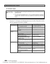
Remove the programmer If the PWR LED becomes normal, the
port connector internal 5 Vdc can be shorted in the
external connections of this port.
Still unlit
Remove the 24 Vdc service If the PWR LED becomes normal, the
power terminals if it is used 24 Vdc service power can be over load.
Still unlit
Remove the option cards and If the PWR LED is still unlit, the T1/T1S
the expansion cable basic unit may be faulty. Replace the unit.
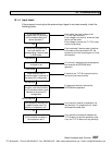
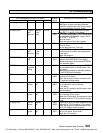
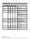
Lit
Confirm the internal 5 Vdc The 5 Vdc capacity for option cards and
current consumption if expansion rack/unit is 1 A.
option card, expansion rack (If the HP911A is connected, it requires
or expansion unit is used 0.2 A, and if RS-485 port is used (T1S),
it requires 0.1 A)
Within the limit
Insert the removed option Replace the faulty option card.
cards one by one to pinpoint
the faulty card
Normal
Connect the expansion rack Replace the faulty I/O module or faulty
or unit again. For expansion expansion rack/unit.
rack, insert the I/O modules
one by one to pinpoint the
faulty module
CTi Automation - Phone: 800.894.0412 - Fax: 208.368.0415 - Web: www.ctiautomation.net - Email: info@ctiautomation.net