


6F3B0250
Basic Hardware and Function
189
7. Instructions
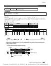
9 devices starting with R200 (R200 to R208) is specified as a shift register.
When R010 is OFF, the data of the shift register is reset to 0. (R200 to R208 are reset to OFF)
The carry flag (CF = S050) is also reset to OFF.
While R010 is ON the following operation is enabled.
·
When X00A is ON (shift left), the data of the shift register is shifted 1 bit to the upper address
direction when X009 is changed from OFF to ON. At the same time, the state of X008 is stored
in the leading bit (R200). The output (R012) indicates the state of the highest bit (R208).
·
When X00A is OFF (shift right), the data of the shift register is shifted 1 bit to the lower address
direction when X009 is changed from OFF to ON. At the same time, the state of X008 is stored
in the highest bit (R208). The output (R012) indicates the state of the lowest bit (R200).
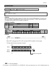
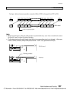
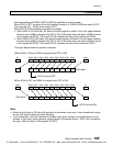
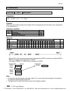
The figure below shows an operation example.
(When X00A is ON and X009 is changed from OFF to ON)
CF R208 R207 R206 R205 R204 R203 R202 R201 R200 X008
100110011 0
1 001100110
R012 is turned OFF
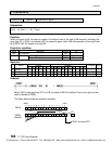
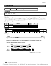
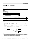
(When X00A is OFF and X009 is changed from OFF to ON)
X008 R208 R207 R206 R205 R204 R203 R202 R201 R200 CF
1 001100110
100110011 0
R012 is turned ON
Note
·
When the shift input is ON, the shift operation is performed every scan. Use a transitional contact
for the shift input to detect the state changing.
·
For the data input, the shift input and the enable input, direct linking to a connecting point is not
allowed. In this case, insert a dummy contact (always ON special device = S04F, etc.) just before
the input. Refer to Note of Shift register FUN 074.
Shift result
Shift result
CTi Automation - Phone: 800.894.0412 - Fax: 208.368.0415 - Web: www.ctiautomation.net - Email: info@ctiautomation.net