


Basic Hardware and Function
285
8. Special I/O Functions
8.7 PWM output function
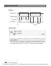
Function
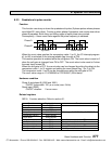
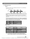
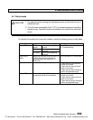
This function is used to output a variable duty cycle pulse train. The controllable duty
cycle is 0 to 100 % (1 % units).
ON duty 50% 70% 60%
PWM
T T T T = Pulse cycle
The PWM output is enabled when the pulse enable flag is ON. While the pulse enable
flag is ON, the duty cycle (ON duty) can be changed by changing the duty setting value (0
to 100).
The frequency setting is available in the range of 50 to 5000 Hz (1 Hz units) before
turning ON the pulse enable flag. The frequency changing is not allowed while the pulse
enable is ON.
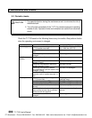
Note that the minimum ON/OFF pulse duration is 100 ms. Therefore, the controllable ON
duty range is limited depending on the frequency setting as follows. If the ON duty setting
value is not available (within 0 to 100), the pulse width error flag comes ON. (PWM output
operation is continued but the duty cycle is not guaranteed)
Frequenc
y
C
y
cle time Available ON dut
y
50 - 100 Hz 20 - 10 ms 0 to 100 %
200 Hz 5 ms 0, 2 to 98, 100 %
1000 Hz 1 ms 0, 10 to 90, 100 %
5000 Hz
200
m
s
0, 50, 100 %
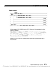
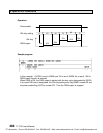
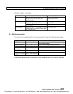
Related registers
SW26: Function selection. Refer to section 8.1.
Function Re
g
ister/
device
Remarks
PWM pulse Y020
Pulse enable fla
g
S270 Output is enabled when ON
Frequenc
y
settin
g
re
g
ister SW28 Data ran
g
e: 50 to 5000
ON dut
y
settin
g
re
g
ister SW29 Data ran
g
e: 0 to 100
Pulse width error fla
g
S26D ON at error (reset OFF automaticall
y
)
ON dut
y
settin
g
error fla
g
S26E ON at error (reset OFF automaticall
y
)
Frequenc
y
settin
g
error fla
g
S26F ON at error (reset OFF automaticall
y
)
Note) If the setting value of SW28 or SW29 is out of the allowable range, the
frequency setting error flag (S26F) or the ON duty setting error flag (S26E)
comes ON. (PWM output operation is continued with previous ON duty setting)
CTi Automation - Phone: 800.894.0412 - Fax: 208.368.0415 - Web: www.ctiautomation.net - Email: info@ctiautomation.net