


6F3B0250
186
T1/T1S User’s Manual
7. Instructions
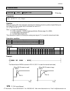
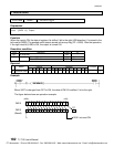
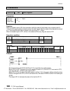
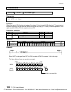
FUN 074 SR Shift register
Expression
Data input
-
D
SR
Q
-
Output
Shift input
-
S
(
n
)
Enable input
-
E
A
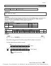
Function
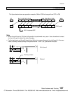
While the enable input is ON, this instruction shifts the data of the bit table, size
n
starting with
A
,
1 bit to the left (upper address direction) when the shift input is ON. The state of the data input is stored
in
A
. The pushed out bit state is stored in the carry flag (CF = S050).
When the enable input is OFF, all bits in the table and the carry flag are reset to OFF.
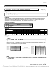
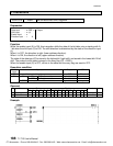
Execution condition
Enable
input
Operation Output CF
OFF Resets all bits in the bit table OFF Reset
ON When the shift input is ON Shift execution Last bit Set or reset
When the shift input is OFF No execution state
-
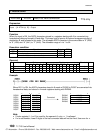
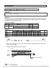
Operand
Name Device Re
g
ister Constant Index
X Y R S T. C. XW YW RW SW T C D I J K
A
Leadin
g
device
ÖÖÖ
n
Device size 1 - 64
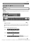
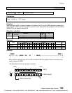
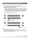
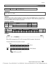
Example
32 devices starting with R100 (R100 to R11F) is specified as a shift register.
When R010 is OFF, the data of the shift register is reset to 0. (R100 to R11F are reset to OFF)
The carry flag (CF = S050) is also reset to OFF.
While R010 is ON, the data of the shift register is shifted 1 bit to the upper address direction when
X009 is changed from OFF to ON. At the same time, the state of X008 is stored in the leading bit
(R100).
The output (R011) indicates the state of the last bit (R11F).
CTi Automation - Phone: 800.894.0412 - Fax: 208.368.0415 - Web: www.ctiautomation.net - Email: info@ctiautomation.net