


6F3B0250
Basic Hardware and Function
25
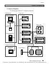
1. System Configuration
¨
¨¨
¨
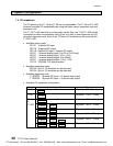
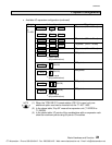
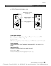
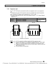
Behind the programmer port cover
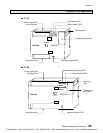
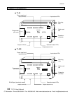
T1-16 / T1-28 T1-40 / T1-40S
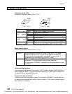
Power supply terminals:
Connect the power cable and grounding wire. The terminal screw size is M3.5.
See sections 4.4 and 4.5 for wiring.
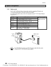
Input terminals:
Connect input signal wires. The terminal screw size is M3.5. See section 2.4 for details.
Output terminals:
Connect output signal wires. The terminal screw size is M3.5. See section 2.4 for
details.
Input status LEDs:
Indicate the ON status of each input signal. (color: red)
Output status LEDs:
Indicate the ON status of each output signal. (color: red)
PRG
R
/
H
V
0
V
1
PRG
H / R
V
1
V
0
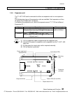
Analog setting adjusters
(V0 and V1)
Mode control switch
(HALT / RUN)
Programmer port
connector
CTi Automation - Phone: 800.894.0412 - Fax: 208.368.0415 - Web: www.ctiautomation.net - Email: info@ctiautomation.net