


6F3B0250
188
T1/T1S User’s Manual
7. Instructions
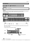
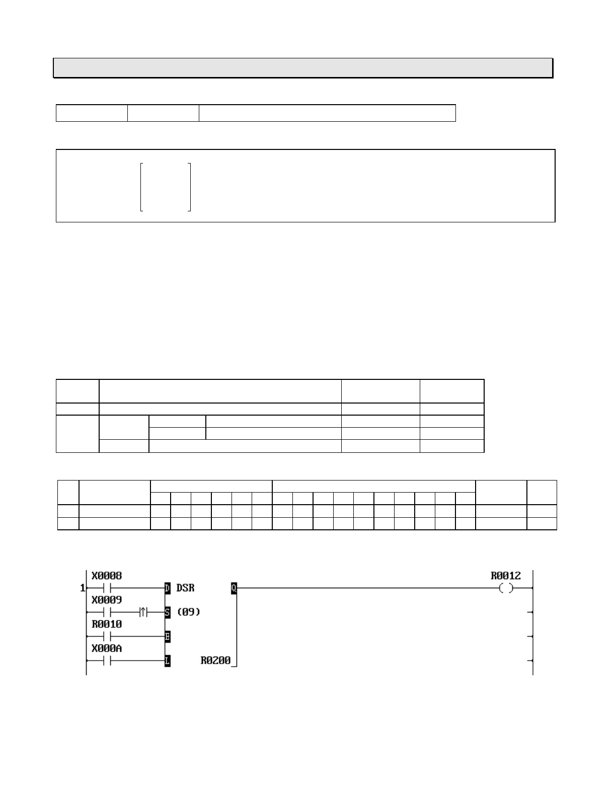
FUN 075 DSR Bi-directional shift register
Expression
Data input
-
D
DSR
Q
-
Output
Shift input
-
S
(
n
)
Enable input
-
E
Direction input
-
L
A
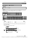
Function
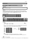
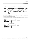
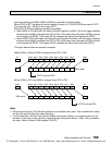
While the enable input (E) is ON, this instruction shifts the data of the bit table, size
n
starting with
A
,
1 bit when the shift input (S) is ON. The shift direction is determined by the state of the direction input
(L).
When L is OFF, the direction is right (lower address direction).
When L is ON, the direction is left (upper address direction).
The state of the data input (D) is stored in the highest bit if right shift, and stored in the lowest bit
A
if left
shift. The pushed out bit state is stored in the carry flag (CF = S050).
When the enable input (E) is OFF, all bits in the table and the carry flag are reset to OFF.
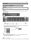
Execution condition
Enable
input
Operation Output CF
OFF Resets all bits in the bit table OFF Reset
ON S = ON L = ON Shift left execution Hi
g
hest bit state Set or reset
L = OFF Shift ri
g
ht execution Lowest bit state Set or reset
S = OFF No execution Hi
g
hest bit state
-
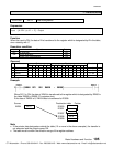
Operand
Name Device Re
g
ister Constant Index
X Y R S T. C. XW YW RW SW T C D I J K
A
Leadin
g
device
ÖÖÖ
n
Device size 1 - 64
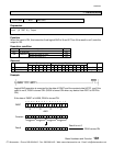
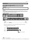
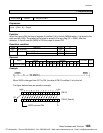
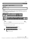
Example
CTi Automation - Phone: 800.894.0412 - Fax: 208.368.0415 - Web: www.ctiautomation.net - Email: info@ctiautomation.net