


5 – Front Panel Operation
52
Examples of Front Panel Programming
You will find these examples on the following pages:
1 Using the front panel display
2 Setting the output voltage, current, and compensation
3 Setting the output 2 voltage and current
4 Querying and clearing output protection
5 Making basic front panel measurements
6 Making enhanced front panel measurements
7 Making DVM measurements
8 Programming the digital port
9 Setting the GPIB address
10 Storing and recalling instrument states
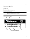
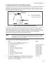
1 - Using the Front Panel Display
Select an output on Agilent 66319B/D units
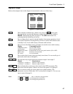
Action Display
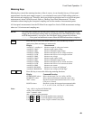
Press Meter to return the display to Meter mode. Press Shift Channel to toggle
between channel 1 and channel 2. The left-most digit of the front panel display
identifies the output channel that is presently being controlled by the front panel. It
will indicate either a "1" for channel 1, or "2" for channel 2.
You can only select an output when the unit is in metering mode. Once an output
has been selected, only the menu commands that apply to that output will appear
on the display. Output -specific menu commands are identified by a 1 or a 2. Also,
the CV, CC, and UNR annunciators apply to the selected channel.
2
7.003V 0.004A
Select the DVM on Agilent 66321D/66319D units
Action Display
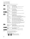
You must select output 1 to use the DVM. If output 1 is not selected, the DVM's
measurement menu is not displayed.
1
8.013V 0.003A
On the Function keypad press Meter and press ( repeatedly to access the DVM
measurement commands. DVM measurement commands are identified by the
"DVM" string segment. When accessed, DVM measurement functions are
automatically active. Refer to example 3 for more information.
1
<reading>V DC:DVM
Independently Control Output 1 and Output 2 on Agilent 66319B/D units
Action Display
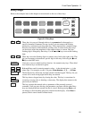
On the Function keypad, press Output. Scroll to the COUPLING command. To
uncouple the outputs, use the # numeric key to select NONE, then press Enter.
COUPLING NONE
2 - Setting the Output Voltage, Current, Resistance, Compensation, and
Relay Mode
This example shows you how to set the output voltage, current, and resistance. It also shows you how to
set the compensation circuit for either high or low capacitance cellular phones. Relay mode only applies
to units that have Option 521 installed. Note that no front panel changes affect the output of the unit
unless it has been enabled.