


Installation - 3
31
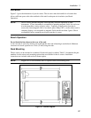
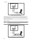
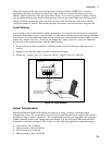
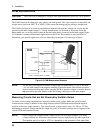
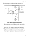
Figure 3-4 shows how to connect remote sense leads when using a removable test fixture. Note that in
this configuration, the wires in the part of the test fixture where the phone is located must be less than 50
cm (20 inches) in length. This is for stability as well as for the fact that the remote sense leads cannot
compensate for the voltage drop in this part of the test fixture.
Programming a negative output resistance lets you compensate for the unsensed voltage drop in the load
leads between the remote sense points and the phone terminals. First, you must measure or calculate the
resistance of the wires between the test fixture and the phone terminals (see table 3-2). Then you can
program the equivalent negative output resistance. This will compensate for the voltage drop in this short
section of wire. Note that the maximum negative resistance that you can program is −40 milliohms.
LOAD
OUTPUT 1
CONNECTOR
+
_
-S - + +S
TWIST LEADS
WIRE RESISTANCE
LENGTH
MUST BE
UNDER 50 CM
(20 INCHES)
TWIST PAIR
FIXTURE
CONNECTIONS
CAN USE NEGATIVE
RESISTANCE
PROGRAMMING TO
COMPENSATE FOR
LEAD RESISTANCE
Figure 3-4. Remote Sense Connections with Test Fixture
NOTE: The built-in overvoltage protection circuit automatically compensates for the voltage
drop between the output terminals and the remote sense lead connections. Refer to "OVP
Considerations" later in this chapter for more information.
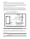
Load Regulation and Voltage Drop in the Remote Sense Leads
The sense leads are part of the dc source's feedback path and must be kept at a low resistance to maintain
optimal performance. One way to accomplish this is to use larger diameter wires for the sense leads (see
Table 3-2).
If this is impractical, you can account for the voltage regulation and readback error that will occur when
using higher resistance remote sense leads. The voltage load regulation and readback error can be
calculated using the following formula:
∆V =
V
LD+
(
R
S+
R
S+
+ 251
)
+ V
LD-
(
R
S-
R
S-
+ 184
)
where: V
LD+
and V
LD-
are the voltage drops in the + and − load leads.
R
S+
and R
S-
are the resistances of the + and − sense leads.