Performance, Calibration, and Configuration - B
153
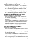
d. Set output 1 to 15 V and repeat step c.
e. Reverse the leads of the external power supply to the DVM inputs. Keep all other connections the
same.
f. With output 1 set to 15 V, lower the voltage on the external power supply until the external (3458)
DMM reads −4.5 V.
g. Record the external (3458) DMM reading and the internal DVM reading. The difference should be
within the negative limits specified for the DVM in Table A-2.
h. Set output 1 to zero volts and repeat step g.
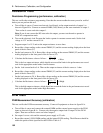
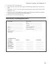
Performance Test Equipment Form
Test Facility:_________________________
Report Number ________________________
____________________________________ Date _________________________________
____________________________________ Customer _____________________________
____________________________________ Tested By ____________________________
Model ______________________________ Ambient Temperature (C) ________________
Serial No. ____________________________ Relative Humidity (%) ___________________
Options _____________________________ Nominal Line Frequency __________________
Firmware Revision ____________________
Special Notes:
Test Equipment Used:
Description Model No. Trace No. Cal. Due Date
AC Source
_________________ _________________ _________________
DC Voltmeter
_________________ _________________ _________________
RMS Voltmeter
_________________ _________________ _________________
Oscilloscope
_________________ _________________ _________________
Electronic Load
_________________ _________________ _________________
Current Shunt
_________________ _________________ _________________
_________________
_________________
_________________


