


Installation - 3
33
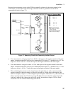
The default setting for the open sense lead protection circuit is disabled or OFF. This is because
applications that apply an external voltage to the output or that use external disconnect relays may
interfere with the operation of the open sense detect circuit. If you are using external voltages or relays,
you can enable the open sense detect at the beginning of the test procedure. Make sure that the external
voltage is disabled and that any relays are in the closed position. Perform the remote sense check by
cycling the output off, then on. Then disable the open sense detect circuit and continue using the unit.
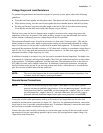
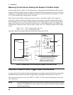
Local Sensing
Local sensing is not recommended for optimal performance. You must use the remote sense connections
on both the main output (output 1) and on output 2 for the unit to operate properly and meet its published
specifications. If you are not using remote sensing and the open sense protection feature is ON, you must
jumper the + output 1 pin to its + sense pin, and jumper the - output 1 pin to its - sense pin. Otherwise,
the unit will go into a protected state with the output disabled.
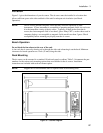
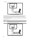
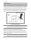
♦ Keep load leads as short as possible. Load leads cannot exceed 18 inches (per side) when local
sensing.
♦ Bundle or twist the leads tightly together to minimize inductance.
♦ Jumper the + output 1 pin to its + sense pin, and the - output 1 pin to its - sense pin.
LOAD
OUTPUT 1/OUTPUT 2
CONNECTOR
+
_
-S - + +S
TWIST LEADS
WIRE RESISTANCE
EACH LEAD MUST
BE LESS THAN 20
INCHES IN LENGTH
JUMPER
Figure 3-5. Local Sensing
Output Compensation
High bandwidth performance and stability are achieved by using a software-switchable output
compensation circuit. This compensation circuit has four bandwidth positions to optimize the response
for different ranges of phone capacitance. The compensation function is set using either the front panel
COMP command located in the Output menu (see chapter 5), or the OUTput:COMPensation:MODE
command as explained in chapter 8. The circuit covers the following approximate capacitance ranges:
♦ LLocal mode: 0 to 12,000 µF
♦ LRemote mode: 2 µF to 12,000 µF
♦ HLocal mode: 0 to 12,000 µF
♦ HRemote mode: 5 µF to 12,000 µF