


B - Performance, Calibration, and Configuration
152
Resistance Tests
Resistance Programming (performance, calibration)
This test verifies the resistance programming. Note that the current readback accuracy must be verified
before you can perform this test.
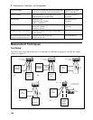
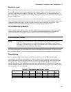
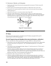
a. Turn off the dc source. Connect an electronic load directly to the output terminals of output 1 as
shown in Figure B-1a. Connect an external DMM (3458) directly to the sense terminals of output 1.
Turn on the dc source and select output 1.
Note: If you do not connect the RC network to the output, you must set the unit to operate in
LLOCAL compensation mode.
b. Turn on the electronic load. Program the load to operate in constant current mode. Set the load
voltage to 15 V and the current to 0 A.
c. Program output 1 to 10 V and set the output resistance to zero ohms.
d. Record the voltage reading on the external DMM (V1) and the current reading displayed on the front
panel of the dc source (I1).
e. Set the load current to 2.8 A. Record the voltage reading on the external DMM (V2) and the current
reading displayed on the front panel of the dc source (I2).
f. Calculate the Resistance value as follows:
V2 − V1
I2 − I1
= Rlow
This is the low output resistance, which should not exceed the limits in the performance test record
card for the appropriate model under Low Resistance.
g. Set the load current back to 0 A. Then set the output resistance of the dc source to 1 ohm.
h. Record the voltage reading on the external DMM (V3) and the current reading displayed on the front
panel of the dc source (I3).
i. Set the load current to 2.8 A. Record the voltage reading on the external DMM (V4) and the current
reading displayed on the front panel of the dc source (I4).
j. Calculate the Resistance value as follows:
V4 − V3
I4 − I3
= Rhigh
This is the high output resistance, which should not exceed the limits in the performance test record
card for the appropriate model under High Resistance.
DVM Tests
DVM Measurement Accuracy (calibration)
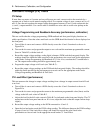
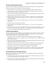
This test verifies the DVM measurement accuracy. Connect all equipment as shown in figure B-1e.
a. Turn off the dc source and connect the external DMM and the external power supply to the DVM
inputs as shown in figure B-1e. Connect only the negative output lead of output 1 to the DVM
inputs. Then turn on the dc source and select output 1.
b. Set output 1 to zero volts and the external power supply to 25 volts.
c. Record the external (3458) DMM reading and the internal DVM reading. The difference should be
within the positive limits specified for the DVM in Table A-2.