


Specifications - A
141
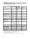
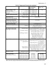
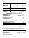
Table A-2. Supplemental Characteristics (continued)
Parameter Agilent 66321B/D;
Agilent 66319B/D
output 1 only
Agilent 66319B/D
output 2 only
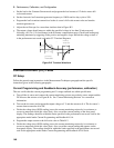
Typical Transient Voltage
Undershoot Values
(actual values are dependent on the
test setup)
With short load leads:
(< 1 meter)
With long load leads:
(up to 6 meters)
30mV w/6µF load cap
25mV w/20µF load cap
40mV w/6µF load cap
30mV w/20µF load cap
NA
Dynamic Measurement System
1
Buffer Length:
Sample Rate Range:
1 − 4096 points
15.6µs − 31200s
NA
Measurement Time
(includes 30 ms
2
acquisition time
and 20 ms processing overhead)
voltage or current 50 ms average
Command Processing Time
(time for output to begin to change
following receipt of digital data)
4 ms average
Savable Instrument States
4 (in locations 0 to 3)
GPIB Interface Capabilities
Language:
Interface:
SCPI
AH1, C0, DC1, DT1, E1,
L4, PP0, RL1, SH1, SR1, T6
FLT Output Characteristics
INH/Trigger Characteristics
Maximum ratings:
FLT Output Terminals:
INH/Trigger Terminals:
16.5 Vdc between terminals 1 and 2; 3 and 4;
and from terminals 1 or 2 to chassis ground
Low-level output current = 1.25 mA max.
Low-level output voltage = 0.5 V max.
Low-level input voltage = 0.8 V max.
High-level input voltage = 2 V min.
Low-level input current = 1 mA
Pulse width = 100 µs minimum
INH time delay = 4 ms typical
Trigger latency = − 15.6 µs to + 32 µs
Digital I/O Characteristics
Maximum ratings:
Digital OUT Port 0,1,2
(open collector)
Digital IN Port 2:
(internal pull-up)
same as FLT/INH/Trigger Characteristics
Output leakage @ 16V = 0.1 mA (ports 0,1)
= 12.5 mA (port 2)
Output leakage @ 5V = 0.1 mA (ports 0,1)
= 0.25 mA (port 2)
Low-level output sink current @ 0.5 V = 4 mA
Low-level output sink current @ 1 V = 50 mA
Low-level input current @ 0.4 V = 1.25 mA
High-level input current @ 5 V = 0.25 mA
Low-level input voltage = 0.8 V max.
High level input voltage = 2.0 V min.
Isolation to Ground
Maximum from either
output terminal to chassis:
50 Vdc
Mains Input Ratings
(at full load from 47–63 Hz)
100 Vac (87-106 Vac):
120 Vac (104-127 Vac):
220 Vac (191-233 Vac):
230 Vac (207-253 Vac):
66321B/D
1.6 A, 125 W
1.4 A, 125 W
0.8 A, 125 W
0.75A, 125 W
66319B/D
2.2 A, 170 W
1.7 A, 170 W
0.96 A, 170 W
0.85A, 170 W
1
For a pulse waveform, the accuracy of any individual data point in the buffer depends on the rise time of the pulse. For a current
pulse of 1.4A with a rise time constant of 50µs, the error in measurement of a single data point during the rise time is ≈ 10mA.
2
May be reduced by changing the default conditions of 2048 data points but measurement uncertainty due to noise will increase.