


3 - Installation
40
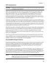
Digital I/O Connections
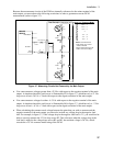
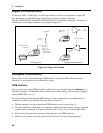
As shown in Table 3-3 and Figure 3-10, the 4-pin connector can also be configured as a digital I/O
port. Information on programming the digital I/O port is found in chapter 5 and under
[SOURce:]DIGital:DATA and [SOURce:]DIGital:FUNCtion commands in chapter 8. The electrical
characteristics of the digital connector are described in appendix A.
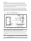
B) Digital Interface Circuits
A) Relay Circuits
INH FLT
. . . .
NOTE: Connectors
are removable
+ - +
Digital Input
Port 2
Relay Driver
Ports 0, 1, 2
(contains internal
clamp diodes for
inductive flyback)
Digital Output
Ports 0, 1, 2
TTL, AS, CMOS, HC
+16.5V Max.
Coil Current
0.25A Max.
4 3 2 1
Figure 3-10. Digital I/O Examples
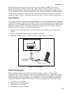
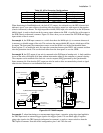
Computer Connections
The dc source can be controlled through a GPIB interface. Follow the GPIB card manufacturer's
directions for card installation and software driver setup.
GPIB Interface
Each dc source has its own GPIB bus address, which can be set using the front panel Address key as
described in chapter 5. GPIB address data is stored in non-volatile memory. The dc source is shipped
with its GPIB address set to 5.
Dc sources may be connected to the GPIB interface in series configuration, star configuration, or a
combination of the two, provided the following rules are observed:
♦ The total number of devices including the GPIB interface card is no more than 15.
♦ The total length of all cables used is no more than 2 meters times the number of devices connected
together, up to a maximum of 20 meters. (Refer to table 2-2 for a list of available GPIB cables.)
♦ Do not stack more than three connector blocks together on any GPIB connector.
♦ Make sure all connectors are fully seated and the lock screws are firmly finger-tightened.