


Performance, Calibration, and Configuration - B
145
Electronic Load
Many of the test procedures require the use of a variable load capable of dissipating the required power.
If a variable resistor is used, switches should be used to either; connect, disconnect, or short the load
resistor. For most tests, an electronic load can be used. The electronic load is considerably easier to use
than load resistors, but it may not be fast enough to test transient recovery time and may be too noisy for
the noise (PARD) tests.
Fixed load resistors may be used in place of a variable load, with minor changes to the test procedures.
Also, if computer controlled test setups are used, the relatively slow (compared to computers and system
voltmeters) settling times and slew rates of the dc source may have to be taken into account. "Wait"
statements can be used in the test program if the test system is faster than the dc source.
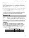
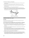
Current-Monitoring Resistor
The 4- terminal current shunt is used to eliminate output current measurement error caused by voltage
drops in the load leads and connections. It has special current-monitoring terminals inside the load
connection terminals. Connect the voltmeter directly to these current-monitoring terminals.
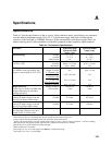
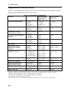
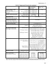
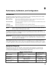
Performance Tests
NOTE: Performance tests verify that the dc source complies with the specifications listed in
Table A-1. Performance tests are indicated by the word "performance" after the test.
Calibration verification tests are used to verify that the unit is within calibration, and are
indicated by the word "calibration" after the test
All of the performance test specifications are entered in the appropriate Performance Test Record Card
for your specific model. You can record the actual measured values in the column provided in this card.
Programming
You can program the dc source from the front panel keyboard or from an GPIB controller when
performing the tests. The test procedures are written assuming that you know how to program the dc
source either remotely from an GPIB controller, or locally using the control keys and indicators on the
front panel. Also, when performing the verification tests from an GPIB controller, you may have to
consider the relatively slow settling times and slew rates of the dc source as compared to computer and
system voltmeters. Suitable WAIT statements can be inserted into the test program to give the dc source
time to respond to the test commands.
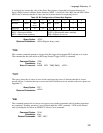
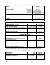
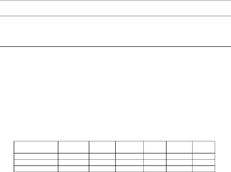
Table B-2. Programming and Output Values
Agilent Model Full scale
Voltage
Vmax Full Scale
Current
Imax Isink OV
Max
66321B/D 15 15.535 3 3.0712 - 2A 22.0
66319B/D output 1 15 15.535 3 3.0712 - 2A 22.0
66319B/D output 2 12 12.25 1.5 1.52 N.A. N.A.