


3 - Installation
38
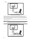
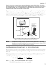
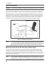
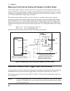
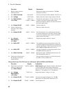
Measuring Circuits that are Floating with Respect to the Main Output
In the example shown in figure 3-8, the common mode voltage between the DVM inputs and the minus
terminal of the main output (output 1) includes an undefined floating voltage that may result in incorrect
readings due to clipping by the internal DVM measurement circuits. This will occur when the −4.5 Vdc
to + 25 Vdc common mode voltage range is exceeded.
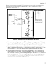
The solution to this problem would be to provide a known or controlled common mode voltage by
connecting a jumper wire from the floating voltage to be measured to the main output. In this example,
the main output is set to 5V, the ac voltage to be measured is approximately 6 Vac (±8.5 Vpeak), and a
jumper wire connects one side of the bias transformer to the + main output terminal. This stabilizes the
common mode voltage and offsets it by the output voltage value (5 V). The peak common mode voltage
is now:
+8.5V + 5 V = +13.5 V on the positive side, and
−8.5V + 5 V = −3.5 V on the negative side;
with both voltages now being within the common mode range of the DVM.
66319D
66321D
OUTPUT 1
+
−
−−
−
DVM INPUT
6 V Bias
Transformer
A
C
A
CC
+ 5 V
6 Vac;
8.5 Vpk
winding capacitance
winding capacitance
GND
GND
Undefined float voltage with respect to
GND due to capacitive currents.
Could be tens of volts ac or more.
Typically, low voltage with respect to
GND due to internal bypass capacitors.
GND
TO
DVM
j
umper wire
stray
capacitance
Figure 3-8. Measuring Circuits Floating with Respect to the Main Output
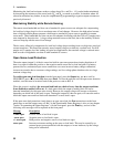
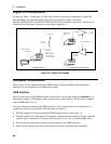
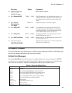
External Protection and Trigger Input Connections
A 4-pin connector and a quick-disconnect mating plug are provided on each instrument for accessing the
Fault/Inhibit functions, the measurement Trigger input, or the Digital I/O functions (see Table 3-3).
The connector accepts wires sizes from AWG 22 to AWG 12. Disconnect the mating plug to make your
wire connections.
NOTE: It is good engineering practice to twist and shield all signal wires to and from the digital
connectors. If shielded wire is used, connect only one end of the shield to chassis ground
to prevent ground loops.