


1 - Quick Reference
12
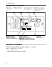
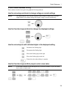
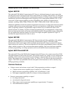
The Rear Panel - At a Glance
1 DVM inputs.
Connector plug is
removable.
2 GPIB (IEEE-488)
interface connector.
3 Used to connect the
Agilent 14575A remote
front panel display.
4 INH/FLT connector. Can
be configured for Digital I/O
and Trigger input. Connector
plug is removable.
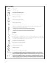
WARNING:
NO OPERATOR SERVICEABLE PARTS REFER SERVICING TO SERVICE TRAINED
WARNING:
FOR CONTINUED FIRE PROTECTION, USE SPECIFIED LINE
-+
+S
INH FLT
+-+
2 3 4
5 6
1
7
-S
OUTPUT 2
0 - 12V / 0 - 1.5A
OUTPUT 1
0 - 15V / 0 - 3A
-S
+S
+-
!
DVM
+-
5 Output 2 connector
(Agilent 66319B/D only).
Connector plug is removable.
6 Output 1 connector.
Connector plug is removable.
IMPORTANT: Install this connector with
its supplied sense jumpers before applying
power to the unit.
7 Power cord
connector (IEC 320)
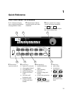
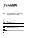
Instrument Configuration
Use the front panel Address key to configure the interface
Refer to “Front Panel Menus - At a Glance”
♦ Enter the GPIB bus address.
♦ Display the firmware revision and serial number.