


25
3
Installation
Installation and Operation Checklist
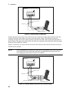
Check the Output Compensation
# Check that the output compensation of the dc source is appropriate for your application. Refer to
“Output Compensation” in this chapter.
HRemote mode provides the best transient response and can be used with phones having input
capacitances from 5µF to 12000µF. Note that if the last two digits on the front panel display are fluctuating
when the phone is in standby, you may want to set the output compensation to a different mode.
LLocal mode offer the best stability with the lowest bandwidth.
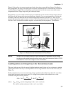
Check the Phone Connections
# If you ARE remote sensing, are the + and −
−−
− sense leads connected ONLY at the test fixture and
within 50 cm of the phone contacts? For best performance, the distance from sense lead termination to
the phone contacts should be as short as possible. Refer to “Remote Sense Connections” in this chapter.
# If you are NOT remote sensing, are the sense jumpers installed in the output connector? Ensure
that the output connector plug is installed in the unit with its supplied sense jumpers in place. Without
sense jumpers, the unit goes into a protect state with the output disabled.
Check the Operating Settings and Conditions
# Are you able to communicate remotely with the dc source? If not, check that the address is set
correctly. Refer to "GPIB Interface" in chapter 2.
# Is the Prot or Err annunciator on the front panel on? If yes, clear the fault condition before
continuing. Refer to “Clearing Output Protection” in chapter 5.
# Is the Overvoltage circuit shutting the unit down? If yes, you can disable the overvoltage circuit.
Refer to “Clearing Output Protection” in chapter 5.
# Is the output load regulation of the unit excessive? If yes, make sure that the output resistance of the
unit is set to zero ohms. Refer to “Output Resistance” in chapter 5.
Check the Measurement Settings
# Are the front panel readings unstable? If yes, check that the front panel sampling rate is correct.
Also
check the setting of the output compensation. Refer to “Making Front Panel Measurements” in chapter 5
and “Output Compensation” in this chapter.
# Are you measuring dynamic output currents? If yes, check that the current detector is set to ACDC.
Refer to “Making Front Panel Measurements” in chapter 5.
# Are you measuring output currents < 1 A or < 20 mA? If yes, check that the current range is set
appropriately. Refer to “Making Front Panel Measurements” in chapter 5.