


3 - Installation
30
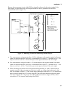
LOAD
TWIST PAIR
OUTPUT 1/OUTPUT 2
CONNECTOR
+
_
-S - + +S
WIRE RESISTANCE
TWIST LEADS
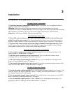
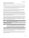
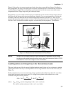
Figure 3-2. Remote Sense Connections
Connect the remote sense leads only to the remote sense connections at the output connector and at the
location on the test fixture where you want to sense the output voltage. There must be not be any
continuity from the sense leads to earth ground or from the sense leads to the output leads other than at
the test fixture. The open sense detect circuit will check for continuity in the sense leads when the output
turned on (from disabled to enabled).
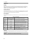
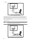
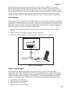
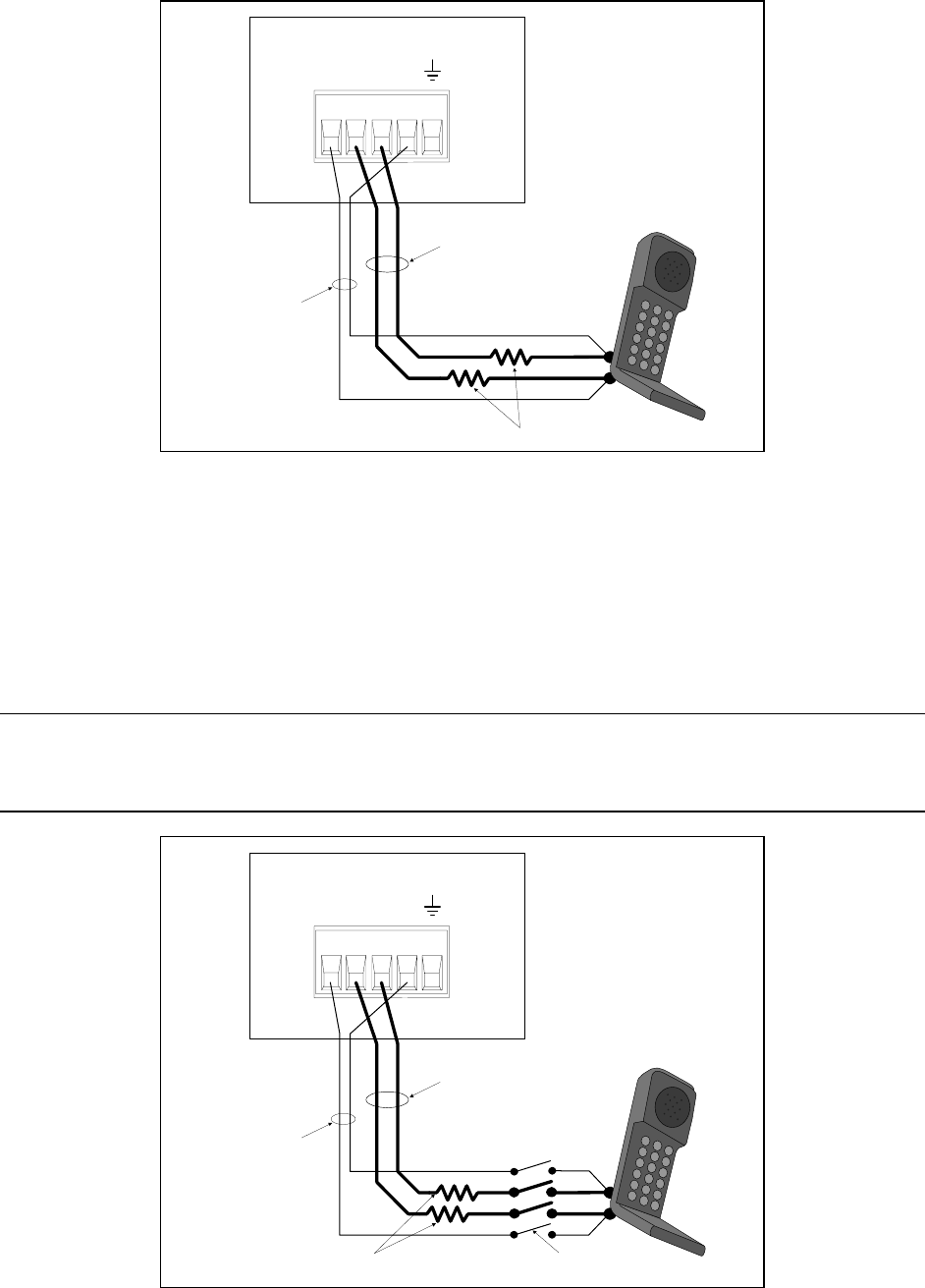
Figure 3-3 shows how to connect remote sense leads and load leads when external disconnect relays are
included in the load path.
NOTE: In this arrangement, the output of the unit should be programmed OFF before the relays
are switched. This is because if the load leads are opened before the sense leads, the
overvoltage protection circuit will trip if it is enabled.
LOAD
OUTPUT 1/OUTPUT 2
CONNECTOR
+
_
-S - + +S
TWIST LEADS
WIRE RESISTANCE
TWIST PAIR
DISCONNECT RELAYS
Figure 3-3. Remote Sense Connections with External Relays