


Performance, Calibration, and Configuration - B
151
CC Source Effect (performance)
This test measures the change in output current that results when the AC line voltage changes from the
minimum to the maximum value within the specifications.
a. Turn off the dc source and connect the ac power line through a variable voltage transformer.
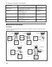
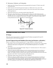
b. Connect the output terminals as shown in Figure B-1b with the DVM connected across the current
monitoring resistor. Set the transformer to the nominal line voltage.
c. Turn on the dc source and program the current to the full scale value and the output voltage to the
maximum programmable value (Vmax) in Table B-2.
d. Adjust the load in the CV mode for full scale voltage as indicated on the front panel display. Check
that the CC annunciator of the UUT is on. If it is not, adjust the load so that the output voltage drops
slightly.
e. Adjust the transformer to the lowest rated line voltage.
f. Record the output current reading (DVM reading/current monitoring resistor in ohms). You may
want to use the average reading program described under “CC Load and Line Regulation”.
g. Adjust the transformer to the highest rated line voltage.
h. Record the output current reading again. The difference in the current readings in steps (f) and (h) is
the CC source effect and should not exceed the values listed in the performance test record card
under CC Source Effect.
CC Noise (performance)
Periodic and random deviations (PARD) in the output combine to produce a residual ac current, as well,
as an ac voltage superimposed on the dc output. Constant current (CC) PARD is specified as the rms
output current in a frequency range 20 Hz to 20 Mhz with the dc source in CC operation.
a. Turn off the dc source and connect the load, monitoring resistor, and rms voltmeter as shown in
Figure B-1b. The current monitoring resistor may have to be substituted by one with a higher
resistance and power rating, such as a 1 ohm 50W, to get the RMS voltage drop high enough to
measure with the RMS voltmeter. Leads should be as short as possible to reduce noise pick-up. An
electronic load may contribute ripple to the measurement so if the RMS noise is above the
specification a resistive load may have to be substituted for this test.
b. Check the test setup for noise with the dc source turned off. Other equipment (e.g. computers,
DVMs, etc.) may affect the reading.
c. Turn on the dc source and program the current to full scale and the output voltage to the maximum
programmable value (Vmax) in Table B-2.
d. The output current should be at the full scale rating with the CC annunciator on.
e. Divide the reading on the rms voltmeter by the current monitor resistance to obtain rms current. It
should not exceed the values listed in the performance test record card under CC Noise (RMS).