


Performance, Calibration, and Configuration - B
147
CV Source Effect (performance)
This test measures the change in output voltage that results from a change in ac line voltage from the
minimum to maximum value within the line voltage specifications.
a. Turn off the dc source and connect the ac power line through a variable voltage transformer.
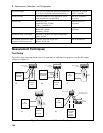
b. Connect the output as shown in Figure B-1a with the DVM connected between the +S and the -S
terminals. Set the transformer to nominal line voltage.
c. Turn on the dc source and program the current to the maximum programmable value (Imax) and the
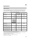
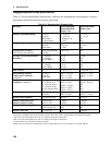
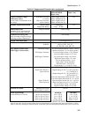
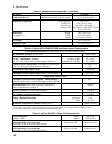
output voltage to the full-scale value in Table B-2.
d. Adjust the load for the full-scale current value in Table B-2 as indicated on the front panel display.
The CV annunciator on the front panel must be on. If it is not, adjust the load so that the output
current drops slightly.
e. Adjust the transformer to the lowest rated line voltage (e.g., 104 Vac for a 115 Vac nominal line
voltage input).
f. Record the output voltage reading on the DVM.
g. Adjust the transformer to the highest rated line voltage (e.g., 127 Vac for 115 Vac nominal line
voltage input).
h. Record the output voltage reading on the DVM. The difference between the DVM reading is steps (f)
and (h) is the source effect voltage and should not exceed the value listed in the performance test
record card for the appropriate model under CV Source Effect.
CV Noise (performance)
Periodic and random deviations (PARD) in the output (ripple and noise) combine to produce a residual
ac voltage superimposed on the dc output voltage. CV PARD is specified as the rms or peak-to-peak
output voltage in the frequency range specified in Appendix A.
a. Turn off the dc source and connect the output as shown in Figure B-1a to an oscilloscope (ac
coupled) between the (+) and the (-) terminals. Set the scope's bandwidth limit to 20 MHz and use an
RF tip on the scope probe.
b. Turn on the dc source and program the current to the maximum programmable value (Imax) and the
output voltage to the full-scale value in Table B-2.
c. Adjust the load for the full-scale current value in Table B-2 as indicated on the front panel display.
d. Note that the waveform on the oscilloscope should not exceed the peak-to-peak limits in the
performance test record card for the appropriate model under CV Noise (PARD).
e. Disconnect the oscilloscope and connect an ac rms voltmeter in its place. The rms voltage reading
should not exceed the RMS limits in the performance test record card for the appropriate model
under CV Noise (PARD).
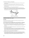
Transient Recovery Time (performance)
This test measures the time for the output voltage to recover to within the specified value following a
50% change in the load current.
a. Turn off the dc source and connect the output as in Figure B-1a with the oscilloscope across the +S
and -S terminals. Remember to connect the RC network.
b. Turn on the dc source and program the output current to the maximum programmable value (Imax)
and the voltage to the full-scale value in Table B-2.