


Installation - 3
29
Voltage Drops and Lead Resistance
To optimize the performance and transient response in your test system, please observe the following
guidelines:
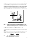
♦ Twist the load leads together and keep them short. The shorter the leads, the better the performance.
♦ When remote sensing, twist the sense leads together but do not bundle them in with the load leads.
♦ For best performance, keep the total cable length to the load to 20 ft or less when remote sensing.
(Note that the unit has been tested with cable lengths of up to 40 feet.)
The load wires must also be of a diameter large enough to avoid excessive voltage drops due to the
impedance of the wires. In general, if the wires are heavy enough to carry the maximum short circuit
current without overheating, excessive voltage drops will not be a problem.
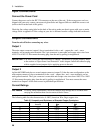
The maximum allowable value of load lead resistance is 4 ohms total (2 ohms per side). This may be
further limited to a lower value, based on peak current loading, by the maximum allowable dc voltage
drop of 8 volts total (4 volts per side) as specified for remote sense operation. To illustrate, for up to 3
amps peak, the maximum allowable resistance is 2.67 ohms total, resulting in a maximum voltage drop of
up to 8 volts. For 5 amps peak the maximum allowable resistance is 1.6 ohms total, again resulting in a
maximum allowable voltage drop of up to 8 volts.
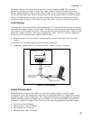
In addition to keeping dc resistance low, you also need to minimize the total impedance. For higher slew
rate currents (0.2 amps/µs) and long wiring lengths (10 to 20 ft.) the inductance can have as much effect
as the resistance. To minimize inductance, twist the load leads. The inductance will be on the order of
0.25 µH/ft if twisted, and 0.4 µH/ft if untwisted. In addition to lowering the inductance, twisting the
leads will reduce noise pick up. If you are using remote sense leads, connect these as a second twisted
pair. Do not twist or bundle them with the load leads.
NOTE: The use of relays between the dc source and the phone also increases impedance. Low
resistance relays will improve system performance.
Remote Sense Connections
NOTE: You must use remote sensing on both Output 1 and Output 2 for the unit to operate
properly and meet its published specifications. If you are not using output 1 and the open
sense protection feature is turned ON, you must jumper the + output 1 pin to its + sense
pin, and jumper the - output 1 pin to its - sense pin. Otherwise, the unit will go into a
protected state and disable the output (unless open sense protection is turned OFF).
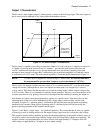
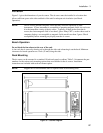
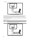
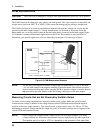
Testing has verified stable performance with up to 20 inches of lead length between the sense lead
termination and the phone connection (see figure 3-4). However, for optimum performance, connect the
sense leads as close as possible to the phone under test. To minimize inductance, connect the sense leads
and load leads as separate twisted pairs (see figure 3-2).
Connect the sense leads carefully so that they do not become open-circuited. If the sense leads are left
unconnected or become open during operation, the dc source will not regulate the output voltage. See
"Open Sense Lead Protection".