


124 Installing System Components
16
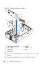
Lift the ZIF levers on processors 1 and 4 to facilitate removing the heat
sink retention bracket.
17
Remove the heat sink retention bracket by removing the eight screws that
hold it to the system board.
18
Disconnect the PWR DIST CONN connectors from the system board at
J9K1 and J9K2.
19
Disconnect the SIGNAL connector from the system board at J9K3.
20
Disconnect the CONTROL PANEL connector from the system board at
J9J1.
21
Reposition the PWR DIST CONN, SIGNAL, and CONTROL PANEL
wiring to facilitate removal of the system board.
22
Disconnect SAS_B connector on the SAS backplane.
23
Lift the system board blue plunger, slide the system board forward to
disengage it from the chassis, and then lift the system board out of the
chassis.
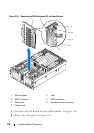
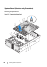
Installing the System Board
CAUTION: Exercise care when removing the system board to prevent damage to
cables, connectors, and components.
1
Ensure power is removed.
2
Position the system board above the chassis with USB, VGA, and serial
connectors at the back of the chassis and with the front edge of the system
board as far forward within the chassis as possible.
3 Tilt the forward edge of the system board down slightly, lower the system
board fully into the chassis, and then slide the system board back until
the system board blue plunger snaps into place.
4
Connect the SIGNAL connector to the system board at J9K3.
5
Connect the PWR DIST CONN connectors to the system board at J9K1
and J9K2.
6
Connect the CONTROL PANEL connector to the system board at J9J1.
7
Connect the SAS_B connector to the SAS backplane.
8
Lift the ZIF levers on processors 1 and 4.