


4-3SectionSR Area
59
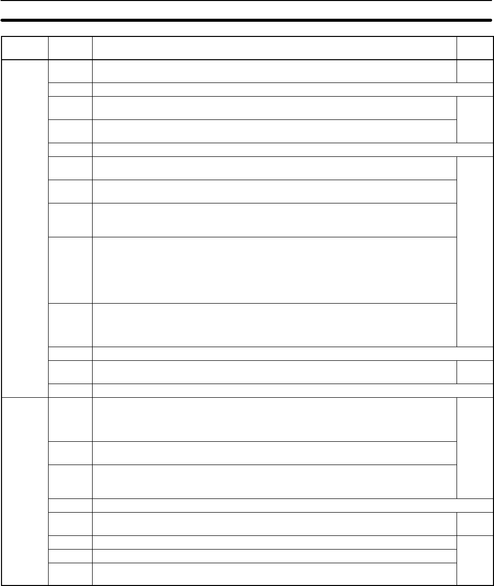
Word(s) Read/
write
FunctionBit(s)
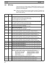
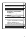
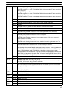
SR 252
00 High-speed Counter Reset Bit Read/
write
01 to 03 Not used.
04 Pulse Output 0 PV Reset Bit
Turn ON to clear the PV of pulse output 0.
Read/
write
05 Pulse Output 1 PV Reset Bit
Turn ON to clear the PV of pulse output 1.
06, 07 Not used.
08 Peripheral Port Reset Bit
Turn ON to reset the peripheral port. Automatically turns OFF when reset is complete.
Read/
write
09 RS-232C Port Reset Bit
Turn ON to reset the RS-232C port. Automatically turns OFF when reset is complete.
10 PC Setup Reset Bit
Turn ON to initialize PC Setup (DM 6600 through DM 6655). Automatically turns OFF
again when reset is complete. Only effective if the PC is in PROGRAM mode.
11 Forced Status Hold Bit (See note.)
OFF:The forced status of bits that are forced set/reset is cleared when switching be-
tween PROGRAM mode and MONITOR mode.
ON: The status of bits that are forced set/reset are maintained when switching between
PROGRAM mode and MONITOR mode.
The PC Setup can be set to maintain the status of this bit when the PC is turned off.
12 I/O Hold Bit (See note.)
OFF:IR and LR bits are reset when starting or stopping operation.
ON: IR and LR bit status is maintained when starting or stopping operation.
The PC Setup can be set to maintain the status of this bit when the PC is turned off.
13 Not used.
14 Error Log Reset Bit
Turn ON to clear error log. Automatically turns OFF again when operation is complete.
Read/
write
15 Not used.
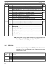
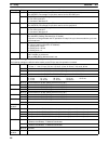
SR 253
00 to 07 FAL Error Code
The error code (a 2-digit number) is stored here when an error occurs. The FAL number
is stored here when FAL(06) or FALS(07) is executed. This word is reset (to 00) by
executing a FAL 00 instruction or by clearing the error from a Programming Device.
Read-
only
08 Battery Error Flag
Turns ON when the CPU Board backup battery’s voltage is too low.
09 Cycle Time Overrun Flag
Turns ON when a cycle time overrun occurs (i.e., when the cycle time exceeds the maxi-
mum cycle time set in the PC Setup).
10,11 Not used.
12 Changing RS-232C Setup Flag
Turns ON when the RS-232C port’s settings are being changed.
Read/
write
13 Always ON Flag
Read-
14 Always OFF Flag
only
15 First Cycle Flag
Turns ON for 1 cycle at the start of operation.