


3-5SectionWiring and Connections
48
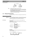
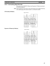
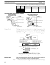
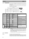
Special functions for input bits IR 00003 through IR 00006 are set in DM 6628:
Bit Bits in
PC Setup setting (in DM 6628)
address DM 6628
0 1 2
IR 00003 00 to 03
Used as normal Used as interrupt Used as
IR 00004 04 to 07
inputs. inputs (including quick-response
IR 00005 08 to 11
counter mode). inputs.
IR 00006 12 to 15
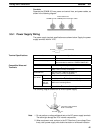
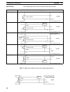
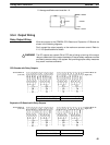
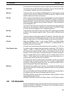
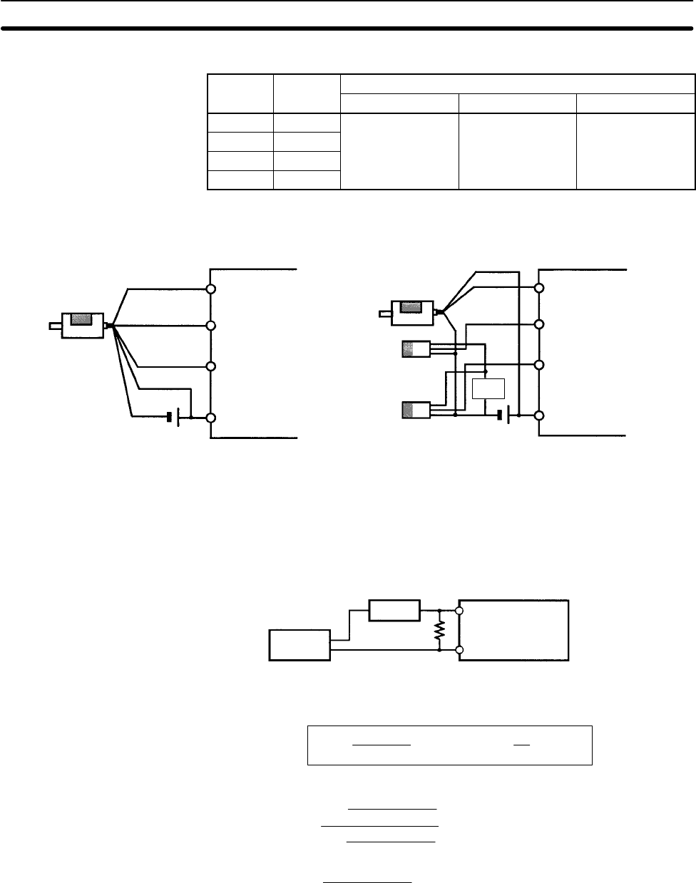
High-speed Counter Input Connection Examples
Differential Phase Mode
(Count frequency: 5 kHz)
E6B2-CWZ6C
Encoder
(NPN open-col-
lector output)
24 V DC
00000 A-phase input
00001 B-phase input
COM
00002 Z-phase input
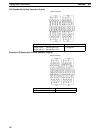
Pulse Plus Direction Input mode
(Count frequency: 20 kHz)
E6A2-CS5C
Encoder
24 V DC
00000 Pulse input
00001 Direction input
COM
00002 Reset input
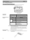
Sensor or
switch
CPM2B CPM2B
Sensor or
switch
Sensor
power
Black
White
Orange
Brown
Blue
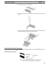
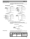
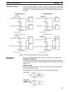
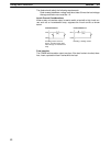
A leakage current can cause false inputs when using 2-wire sensors (proximity
switches or photoelectric switches) or limit switches with LEDs. False inputs
won’t occur if the leakage current is less than 1.0 mA (2.5 mA for IN00000 to
IN00002). If the leakage current exceeds these values, insert a bleeder resistor
in the circuit to reduce the input impedance, as shown in the following diagram.
R
CPM2B
Input power
supply
Bleeder
resistor
2-wire sensor, etc.
I: Device’s leakage current (mA)
R: Bleeder resistance (kΩ)
W: Bleeder resistor’s power rating (W)
The equations above were derived from the following equations:
L
C
: CPM2B’s input impedance (kΩ)
I
C
: CPM2B’s input current (mA)
E
C
: CPM2B’s OFF voltage (V) = 5.0 V
R +
L
C
5.0
I L
C
–5.0
kW max.
W +
2.3
R
Wmin.
I
R
Input voltage (24)
Input Current (I
C
)
R )
Input voltage (24)
Input Current (I
C
)
x OFF voltage (E
C
:5.0)
W y
Input voltage (24)
R
Input voltage (24) tolerance (4)
Refer to 2-1-3 I/O Specifications for details on the values L
C
, I
C
, and E
C
.
The input impedance, input current, and OFF voltage may vary depending on the
input being used. (IN00000 through IN00002 have different values.)
When connecting an inductive load to an input, connect a diode in parallel with
the load. The diode should satisfy the following requirements:
1, 2, 3... 1. Peak reverse-breakdown voltage must be at least 3 times the load voltage.
Leakage Current
Inductive Loads