


2-1SectionSpecifications
24
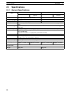
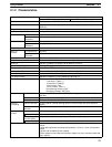
Item CPU BoardsItem
With transistor outputsWith relay outputs
Synchronized pulse control 1 point:
A pulse output can be created by combining the high-speed counter with pulse
outputs and multiplying the frequency of the input pulses from the high-speed
counter by a fixed factor.
(This output is possible with transistor outputs only, it cannot be used with relay
outputs.)
Quick-response inputs 4 points (Min. input pulse width: 50 µs max.) (Also used for interrupt inputs and for
interrupt inputs in counter mode.)
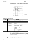
Input time constant
(ON response time = OFF response
time)
Can be set for all input points.
(1 ms, 2 ms, 3 ms, 5 ms, 10 ms, 20 ms, 40 ms, or 80 ms)
Clock function Shows the year, month, day of the week, day, hour, minute, and second.
(Backed up by the battery.)
(The clock function is available only in CPU Boards equipped with a clock.)
Communications functions Built-in peripheral port:
Supports Host Link, peripheral bus, no-protocol, or Programming Console
connections.
Built-in RS-232C port:
Supports Host Link, no-protocol, 1:1 PC Link (Master/Slave), or 1:1 NT Link
connections.
(RS-232C communications are available only in CPU Boards equipped with an
RS-232C port.)
Memory protection
(See notes 1 and 2.)
HR area, AR area, program contents, read/write DM area contents, and counter
values maintained during power interruptions.
Memory backup
(See notes 1 and 2.)
Flash memory:
Program, read-only DM area, and PC Setup
Battery or capacitor backup:
The read/write DM area, HR area, AR area, and counter values are backed up by
a battery.
CPU Boards with clock: Backup is approximately 5 years at 25°C.
CPU Boards without clock:Backup is approximately 5 days at 25°C.
Self-diagnostic functions CPU error (watchdog timer), I/O bus error, battery error, and memory error
Program checks No END instruction, programming errors (checked when operation is started)
Note 1. The DM area, HR area, AR area, and counter values are backed up by the
CPU Board’s built-in battery or capacitor. If the battery or capacitor is dis-
charged, the contents of these areas will be lost and the data values will re-
vert to the defaults.
2. The contents of the program area, read-only DM area (DM 6144 to
DM 6599), and PC Setup (DM 6600 to DM 6655) are stored in flash
memory. The contents of these areas will be read from flash memory the
next time the power is turned ON, even if the backup battery or capacitor is
discharged.
When data has been changed in any of these areas, write the new values to
flash memory by switching the CPM2B to MONITOR or RUN mode, or by
turning the power OFF and then ON again.