


4-1SectionIntroduction
54
4-1 Introduction
Most data areas in the CPM2B can be accessed as bits or words. (The TR area
can be accessed by bit address only and the DM area can be accessed by word
address only.)
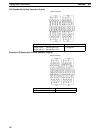
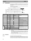
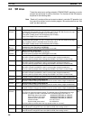
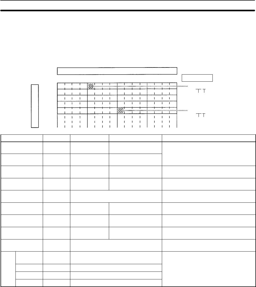
The following diagram shows the structure of the IR area and the relationship
between bit and word addresses.
Bit number
IR 000
IR 001
IR 010
IR 011
IR 00011
Word
Bit number
IR 01107
Word Bit number
Word addresses
Bit addresses
15 14 13 12 11 10 9 8 7 6 5 4 3 2 1 0
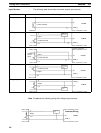
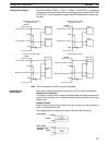
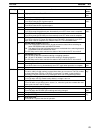
Data area Size Words Bits Function
Input area 160 bits
(10 words)
IR 000 to IR 009 IR 00000 to IR 00915
(See note 1.)
These bits can be allocated to the external
I/O terminals.
Output area 160 bits
(10 words)
IR 010 to IR 019 IR 01000 to IR 01915
Work area 928 bits
(58 words)
IR 020 to IR 049
IR 200 to IR 227
IR 02000 to IR 04915
IR 20000 to IR 22715
Work bits can be freely used within the
program.
SR area 448 bits
(28 words)
SR 228 to
SR 255
SR 22800 to SR 25515 These bits serve specific functions such as
flags and control bits.
TR area 8 bits TR 0 to TR 7 These bits are used to temporarily store
ON/OFF status at program branches.
HR area 320 bits
(20 words)
HR 00 to HR 19 HR 0000 to HR 1915 These bits store data and retain their
ON/OFF status when power is turned off.
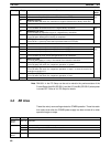
AR area 384 bits
(24 words)
AR 00 to AR 23 AR 0000 to AR 2315 These bits serve specific functions such as
flags and control bits.
LR area 256 bits
(16 words)
LR 00 to LR 15 LR 0000 to LR 1515 Used for a 1:1 data link with another PC.
Timer/Counter
area
256 bits TIM/CNT 000 to TIM/CNT 255 The same numbers are used for both
timers and counters.
DM
area
Read/write 2,026
words
DM 0000 to DM 1999
DM 2022 to DM 2047
DM area data can be accessed in word
units only. Word values are retained when
Error log 22 words DM 2000 to DM 2021
the power is turned off.
Read-only 456 words DM 6144 to DM 6599
The read-only area and PC Setup cannot
PC Setup 56 words DM 6600 to DM 6655
be overwritten from program. Change
these settings with a Programming Device.
Note 1. Input bits IR 00108 to IR 00111 reflect the status of the DIP switch on the
CPU Board.
2. The contents of the HR area, AR area, Counter area, and read/write DM
area are backed up by the CPU Board’s backup battery or capacitor. If the
battery or capacitor discharges completely, memory contents will be re-
turned to their default settings.
3. The program and data in DM 6144 to DM 6655 are stored in flash memory.
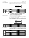
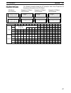
4-1-1 Functions
The functions of the IR area are explained below.
IR area bits in the input and output areas are allocated to terminals on the CPU
Board and Expansion I/O Boards. They reflect the ON/OFF status of input and
output signals. Input bits begin at IR 00000, and output bits begin at IR 01000.
IR Area