


3-5SectionWiring and Connections
41
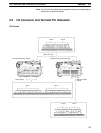
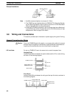
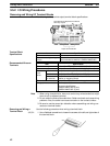
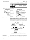
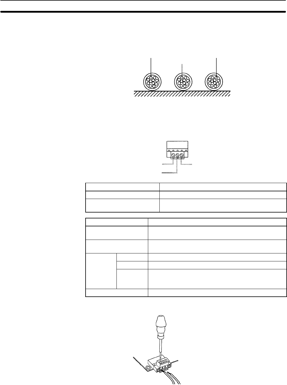
Conduits
Separate the CPM2B I/O lines, power and control lines, and power cables, as
shown in the following diagram.
CPM2B I/O lines
Control cables and
CPM2B power lines
Power cables
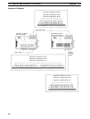
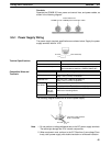
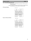
3-5-1 Power Supply Wiring
The power supply terminal specifications are shown below. Supply the power
supply terminals with 24 V DC.
24 V DC (Not connected)
0 V
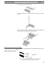
Item Specifications
Screw size M3
Recommended torque
0.5 to 0.6 NSm
Recommended screwdriver: OMRON XW4E-00C
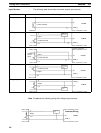
Wire/terminal Specification
Solid wire 0.2 to 2.5 mm
2
(AWG 24 to AWG 12)
Strip 7 mm (1/4 inch) of insulation.
Stranded wire 0.2 to 2.5 mm
2
(AWG 24 to AWG 12)
Strip 7 mm (1/4 inch) of insulation.
Two-condu
Solid 2 × (0.2 to 1.0 mm
2
) (AWG 24 to AWG 20)
ctor wires
Stranded 2 × (0.2 to 1.5 mm
2
) (AWG 24 to AWG 16)
Stranded
with pin
terminal
2 × (0.25 to 1.0 mm
2
) (AWG 24 to AWG 20)
without an insulating sleeve
Pin terminals 0.2 to 2.5 mm
2
diameter, 7-mm long pin terminal
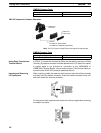
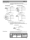
The following diagram shows how to wire the power supply.
The power supply terminal
block is removable.
24 V DC 0 V
Note 1. Do not perform a voltage withstand test on the DC power supply terminals.
The test might damage the PC’s internal components.
2. When equipment must conform to the EC Directives (Low-voltage Direc-
tives), use a power supply with double insulation or reinforced insulation.
Terminal Specifications
Compatible Wires and
Terminals