


1-1SectionCPM2B Features and Functions
3
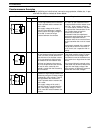
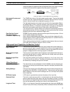
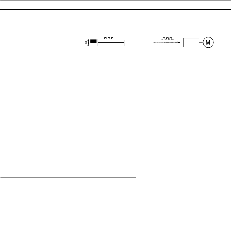
lowing the speed of a peripheral piece of equipment (such as a supply conveyor)
to be synchronized with the speed of the main piece of equipment.
Encoder
CPM2B
Motor driver Motor
Pulses are output as a fixed multiple of the input frequency.
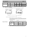
The CPM2B has a total of five high-speed counter inputs. The one high-speed
counter input has a response frequency of 20 kHz/5 kHz and the four interrupt
inputs in counter mode have a response frequency of 2 kHz.
The high-speed counter can be used in any one of the four input modes: differen-
tial phase mode (5 kHz), pulse plus direction input mode (20 kHz), up/down
pulse mode (20 kHz), or increment mode (20 kHz). Interrupts can be triggered
when the count matches a set value or falls within a specified range.
The interrupt inputs in counter mode can be used for incrementing counters or
decrementing counters (2 kHz) and trigger an interrupt (executing the interrupt
program) when the count matches the target value.
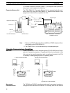
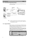
CPM2B PCs with transistor outputs have two outputs that can produce 10 Hz to
10 kHz pulses (single-phase outputs).
When used as single-phase pulse outputs, there can be two outputs with a fre-
quency range of 10 Hz to 10 kHz with a fixed duty ratio or 0.1 to 999.9 Hz with a
variable duty ratio (0 to 100% duty ratio).
When used as pulse plus direction or up/down pulse outputs, there can be just
one output with a frequency range of 10 Hz to 10 kHz.
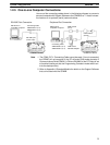
High-speed Input Capabilities for Machine Control
There are four inputs used for interrupt inputs (shared with quick-response in-
puts and interrupt inputs in counter mode) with a minimum input signal width of
50 µs and response time of 0.3 ms. When an interrupt input goes ON, the main
program is stopped and the interrupt program is executed.
There are four inputs used for quick-response inputs (shared with interrupt in-
puts and interrupt inputs in counter mode) that can reliably read input signals
with a signal width as short as 50 µs.
The input time constant for all inputs can be set to 1 ms, 2 ms, 3 ms, 5 ms,
10 ms, 20 ms, 40 ms, or 80 ms. The effects of chattering and external noise can
be reduced by increasing the input time constant.
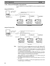
Other Functions
The interval timer can be set between 0.5 and 319,968 ms and can be set to gen-
erate just one interrupt (one-shot mode) or periodic interrupts (scheduled inter-
rupt mode).
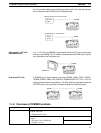
There are two controls on the CPU Board that can be turned to change the ana-
log settings (0 to 200 BCD) in IR 250 and IR 251. These controls can be used to
easily change or fine-tune machine settings such as a conveyor belt’s pause
time or feed rate.
A DIP switch is provided that controls the status of four input bits.
The built-in clock (accuracy within 1 minute/month) can be read from the pro-
gram to show the current year, month, day, day of the week, and time. The clock
can be set from a Programming Device (such as a Programming Console) or the
time can be adjusted by rounding up or down to the nearest minute.
TIML(––) is a long-term timer that accommodates set values up to 99,990 sec-
onds (27 hours, 46 minutes, 30 seconds). When combined with the SECONDS
High-speed Counters and
Interrupts
Easy Position Control
with Pulse Outputs
(Transistor Outputs Only)
High-speed Interrupt
Input Function
Quick-response Input
Function
Stabilizing Input Filter
Function
Interval Timer Interrupts
Analog Settings
DIP Switch Inputs
Calendar/Clock
Long-term Timer