


3-5SectionWiring and Connections
46
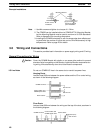
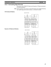
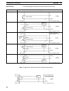
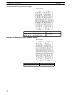
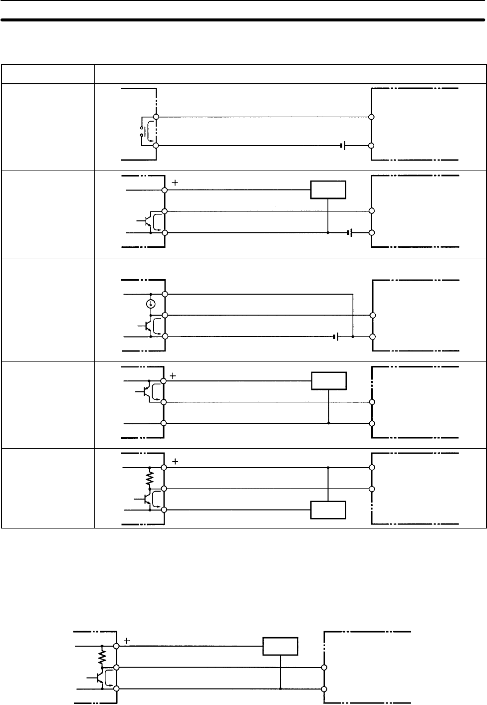
The following table shows how to connect various input devices.
Device Circuit diagram
Relay output
IN
COM (+)
5 mA/6 mA/8 mA
CPM2B
NPN open collector
IN
COM (+)
Sensor
power supply
Output
5 mA/6 mA/8 mA
CPM2B
0 V
NPN current output
Use the same power supply for
the input and sensor.
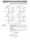
CPM2BIN
COM (+)
Output
5 mA/6 mA/8 mA
0 V
Constant
current
circuit
+
PNP current output
Sensor power
supply
COM (–)
0 V
IN
Output
5 mA/6 mA/8 mA
CPM2B
Voltage output
Sensor power
supply
IN
COM (+)
0 V
Output
CPM2B
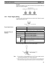
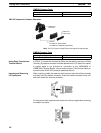
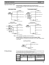
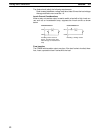
Note Do not use the following wiring with voltage-output devices:
COM(+)
IN
0 V
Output
CPM2B
Sensor power
supply
Incorrect Wiring
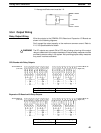
Input Devices