


2-1SectionSpecifications
26
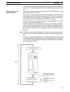
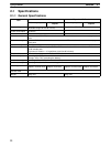
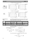
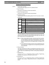
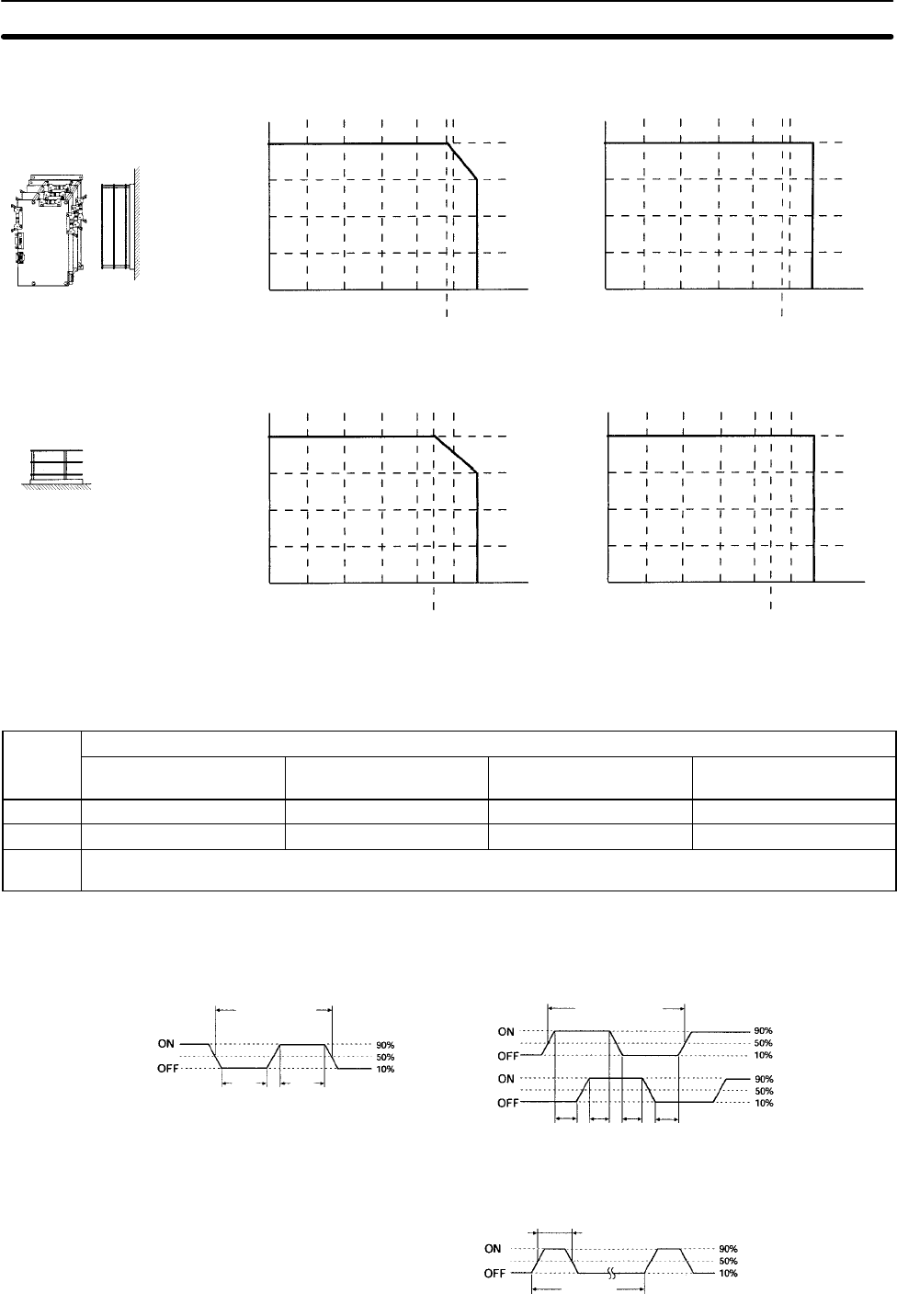
2. Installation orientation: Vertical with end down
Input voltage
26.4 V DC
Input voltage
24 V DC
Max. number of inputs ON
at the same time
16
14
Max. number of inputs ON
at the same time
16
14
0102030405055
49
(°C)
0102030405055
49
(°C)
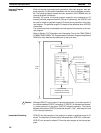
3. Installation orientation: Horizontal
Input voltage
26.4 V DC
Max. number of inputs ON
at the same time
16
13
0102030405055
45
(°C)
Input voltage
24 V DC
Max. number of inputs ON
at the same time
16
13
0102030405055
45
(°C)
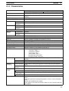
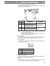
Inputs IN00000 through IN00002 can be used as high-speed counter inputs, as
shown in the following table. The maximum count frequency is 5 kHz in differen-
tial phase mode and 20 kHz in the other modes.
Input
Function
Differential phase mode Pulse plus direction
input mode
Up/down input mode Increment mode
IN00000 A-phase pulse input Pulse input Increment pulse input Increment pulse input
IN00001 B-phase pulse input Direction input Decrement pulse input Normal input
IN00002 Z-phase pulse input or hardware reset input
(IN00002 can be used as a normal input when it is not used as a high-speed counter input.)
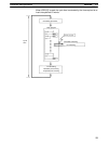
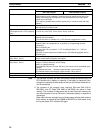
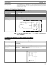
The minimum pulse widths for inputs IN00000 (A-phase input) and IN00001 (B-
phase input) are as follows:
100 µs min.
T
1
T
2
T
3
T
4
: 12.5 µs min.
Phase A
Phase B
50 µs min.
12.5 µs
min.
Pulse plus direction input mode, Up/down input
mode, Increment mode
Differential phase mode
12.5 µs
min.
T
1
T
2
T
3
T
4
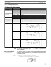
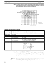
The minimum pulse width for input IN00002 (Z-phase input) is as follows:
50 µs min.
500 µs
min.
Phase Z
High-speed Counter
Inputs