


4-2SectionI/O Allocation
57
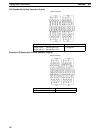
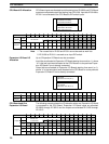
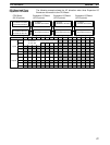
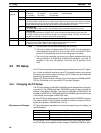
The following example shows the I/O allocation when three Expansion I/O
Boards are connected to the CPU Board.
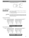
16 inputs
IR 00000 to IR 00007
IR 00100 to IR 00107
16 outputs
IR 01000 to IR 01007
IR 01100 to IR 01107
Inputs
IR 000
IR 001
15 14 13 12 11 10 09 08 07 06 05 04 03 02 01 00
Outputs
IR 010
IR 011
16 inputs
IR 00200 to IR 00215
16 outputs
IR 01200 to IR 01215
CPU Board
(32 I/O points)
Expansion I/O Board
(32 I/O points)
Do not use
as work bits.
Expansion I/O Board
(32 I/O points)
Expansion I/O Board
(32 I/O points)
IR 012
IR 013
IR 014
IR 002
IR 003
IR 004
Bits
16 inputs
IR 00300 to IR 00315
16 outputs
IR 01300 to IR 01315
16 inputs
IR 00400 to IR 00415
16 outputs
IR 01400 to IR 01415
CPU Board and Three
Expansion I/O Boards