


4-2SectionI/O Allocation
56
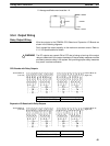
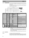
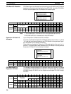
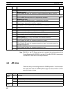
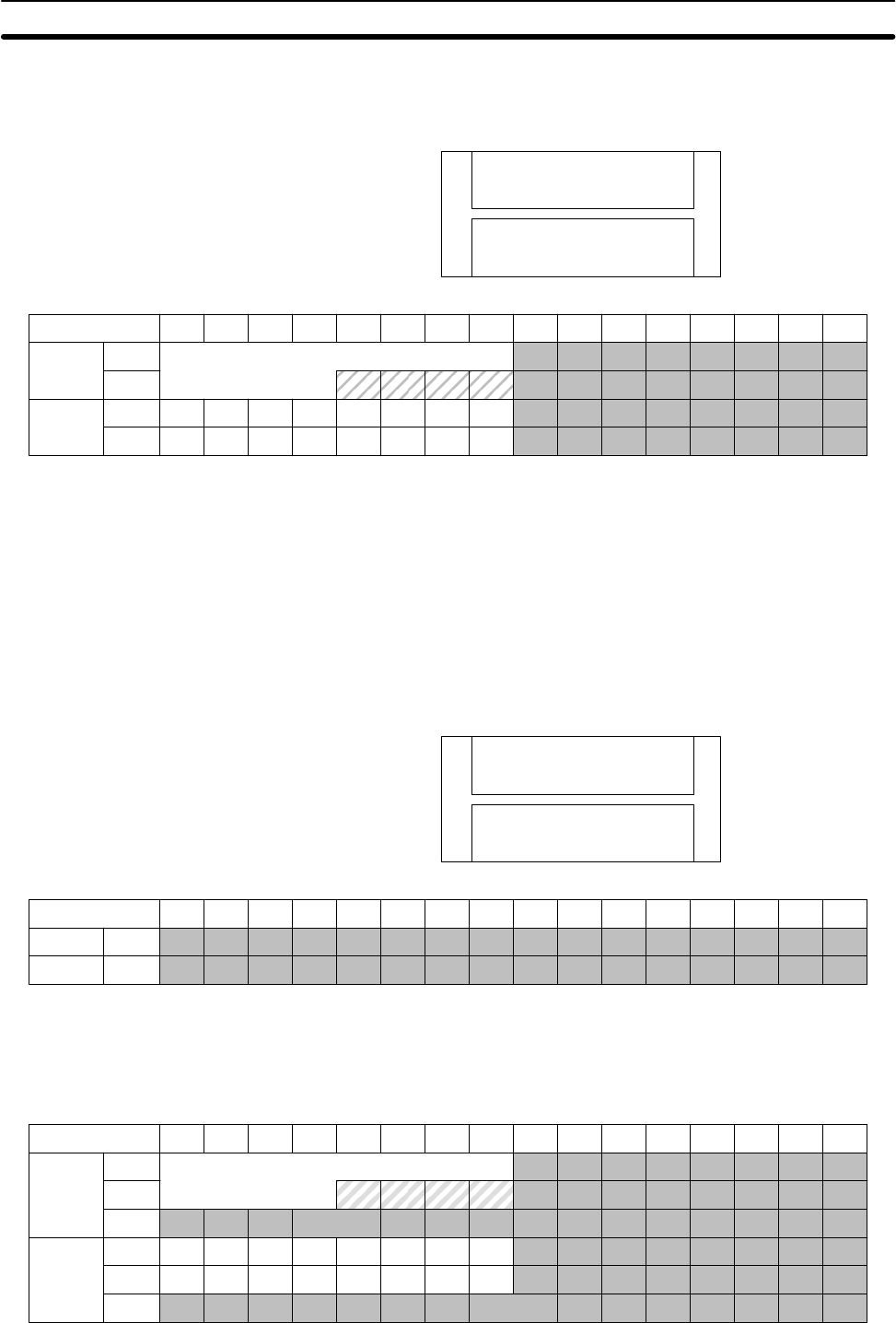
CPU Board inputs are allocated input bits starting from IR 00000 and CPU Board
outputs are allocated output bits starting from IR 01000. Input bits IR 00108 to
IR 00111 are allocated to the CPU Board’s DIP switch inputs.
16 inputs
IR 00000 to IR 00007
IR 00100 to IR 00107
16 outputs
IR 01000 to IR 01007
IR 01100 to IR 01107
Inputs
IR 000
IR 001
15 14 13 12 11 10 09 08 07 06 05 04 03 02 01 00
Outputs
IR 010
IR 011
Do not use
Bits
Note 1. The unused bits in IR 000 and IR 001 cannot be used as work bits.
2. IR 00108 to IR 00111 are used as an input DIP switch.
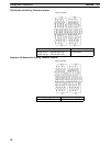
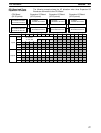
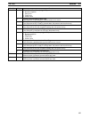
Up to 3 Expansion I/O Boards can be connected.
Input bits are allocated to Expansion I/O Boards starting from word (m+1), where
“m” is the last input word allocated to the CPU Board or to the previous Expan-
sion I/O Board if one is already connected.
Output bits are allocated to Expansion I/O Boards starting from word (n+1),
where “n” is the last output word allocated to the CPU Board or to the previous
Expansion I/O Board if one is already connected.
16 inputs
Bits 00 to 15 in IR (m+1)
16 outputs
Bits 00 to 15 in IR (n+1)
Inputs
Outputs
m+1
n+1
15 14 13 12 11 10 09 08 07 06 05 04 03 02 01 00
Bits
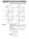
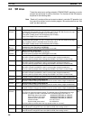
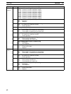
The following example shows the I/O allocation when one Expansion I/O Board
is connected to the CPU Board. Expansion I/O Board inputs are allocated
IR 00200 through IR 00215 and the outputs are allocated IR 01200 through
IR 01215.
Inputs
IR 000
IR 001
15 14 13 12 11 10 09 08 07 06 05 04 03 02 01 00
Outputs
IR 010
IR 011
Do not use
as work bits.
IR 002
IR 012
Bits
CPU Board I/O Allocation
Expansion I/O Board I/O
Allocation
CPU Board and One
Expansion I/O Board