


!
2-1SectionSpecifications
28
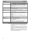
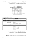
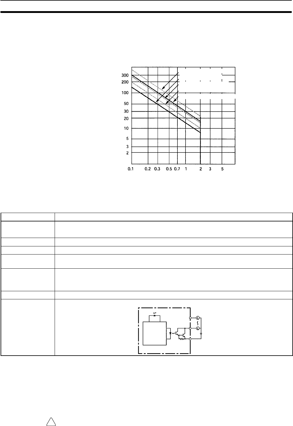
Note The service life of the CPM2B’s relay output contacts shown in the table as-
sumes the worst conditions. The following graph shows the results of OMRON’s
service life tests at a switching rate of 1,800 times/hour.
Life (x 10
4
)
Contact current (A)
120 V AC, resistive load
24 V DC/240 V AC, resistive load
Switching rate:
1,800 times/hour
24 V DC, τ = 7 ms
120 V AC, cosφ = 0.4
240 V AC, cosφ = 0.4
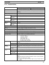
Transistor Outputs (Sinking or Sourcing)
Item Specification
Max. switching
capacity
OUT01000 and OUT01001: 4.5 to 30 V DC, 0.2 A/output (See note 1.)
OUT01002 and up: 4.5 to 30 V DC, 0.3 A/output (See note 1.)
Leakage current 0.1 mA max.
Residual voltage 1.5 V max.
ON delay OUT01000 and OUT01001: 20 µs max.
OUT01002 and up: 0.1 ms max.
OFF delay OUT01000 and OUT01001: 40 µs max. for 4.5 to 26.4 V, 10 to 100 mA
0.1 ms max. for 4.5 to 30 V, 10 to 200 mA
OUT01002 and up: 1 ms max. for 4.5 to 30 V, 10 to 300 mA
Fuse 1 fuse/output (cannot be replaced by user)
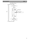
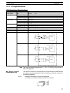
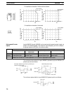
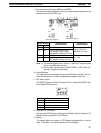
Circuit configuration
Sinking Outputs
COM (–)
Output LED
Internal
circuits
OUT
OUT
24 V DC
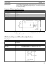
Note When using OUT01000 or OUT01001 for pulse outputs, connect a dummy re-
sistor as required to bring the load current between 0.01 and 0.1 A. If the load
current is below 0.01 A, the ON-to-OFF response time will be too long and high-
speed pulses will not be output.
Caution Do not apply voltage in excess of the maximum switching capacity to an output
terminal. It may result in damage to the product or fire.