


1-3SectionStructure and Operation
13
1-3 Structure and Operation
1-3-1 CPU Board Structure
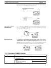
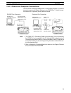
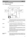
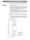
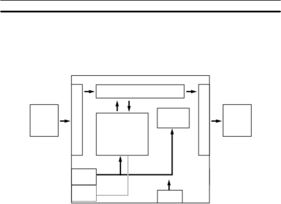
The following diagram shows the internal structure of the CPU Board.
External
input
devices
I/O memory
Program
PC Setup
RS-232C
port
Settings
Settings
Settings
External
output
devices
Communica-
tions switch
Input circuits
Output circuits
Peripheral
port
The program reads and writes data in this memory area during execution. Part of
the I/O memory contains the bits that reflect the status of the PC’s inputs and
outputs. Parts of the I/O memory are cleared when the power is turned ON and
other parts are retained.
Note Refer to Section 4 Memory Areas for more details on I/O memory.
This is the program written by the user. The CPM2B executes the program cycli-
cally. (Refer to 1-3-5 Cyclic Operation and Interrupts for details.)
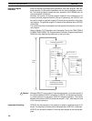
The program can be divided broadly into two parts: the “main program” that is
executed cyclically and the “interrupt programs” that are executed only when the
corresponding interrupt is generated.
The PC Setup contains various startup and operating parameters. The PC Set-
up parameters can be changed from a Programming Device only; they cannot
be changed from the program.
Some parameters are accessed only when PC’s power supply is turned on and
others are accessed regularly while the power is on. It will be necessary to turn
the power off and then on again to enable a new setting if the parameter is ac-
cessed only when the power is turned on.
Note Refer to 4-5 PC Setup for more details.
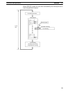
The Communications Switches determine whether the peripheral port and
RS-232C port operate with the standard communications settings or the com-
munications settings in the PC Setup. Refer to 2-2 Board Components and their
Functions for more details.
I/O Memory
Program
PC Setup
Communications
Switches