2-2SectionBoard Components and their Functions
30
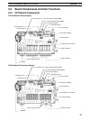
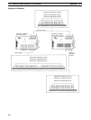
CPU Board Component Descriptions
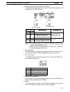
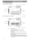
1, 2, 3... 1. Power Supply Terminals
Connect the power supply (24 V DC) to these terminals.
2. Input Connector
Connects the CPU Board to external input devices.
3. Output Terminals/Connector
Connects the CPU Board to external output devices.
4. PC Status Indicators
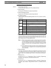
These indicators show the operating status of the PC, as shown in the fol-
lowing table.
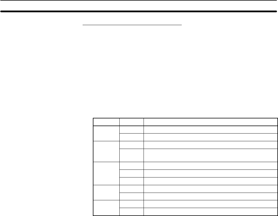
Indicator Status Meaning
PWR
Lit Power is being supplied to the PC.
(green)
Not lit Power isn’t being supplied to the PC.
RUN
Lit The PC is operating in RUN or MONITOR mode.
(green)
Not lit The PC is in PROGRAM mode or a fatal error has
occurred.
ERR
Lit A fatal error has occurred. (PC operation stops.)
(red)
Flashing A non-fatal error has occurred. (PC operation continues.)
Not lit Indicates normal operation.
PERI
Flashing Data is being transferred through the peripheral port.
(orange)
Not lit The peripheral port is not in use.
COMM
Flashing Data is being transferred through the RS-232C port.
(orange)
Not lit The RS-232C port is not in use.
5. Input Indicators
The input indicators are lit when the corresponding input terminal is ON. The
status of an input indicator will reflect the status of the input even when that
input is being used for a high-speed counter.
Note a) When interrupt inputs are used in interrupt input mode, the indica-
tor may not light even when the interrupt condition is met if the in-
put is not ON long enough. When a high-speed counter is being
used, the indicator may not light depending on the speed of the
pulses.
b) Input indicators will reflect the status of the corresponding inputs
even when the PC is stopped, but the corresponding input bits will
not be refreshed.
6. Output Indicators
The output indicators are lit when the corresponding output terminal is ON.
The indicators are lit during I/O refreshing. When an output is being used as
a pulse output, the corresponding will remain lit while pulses are being out-
put.
7. Peripheral Port
Connects the PC to a Programming Device (including Programming
Consoles), host computer, or standard external device.
8. RS-232C Port
Connects the PC to a Programming Device (excluding Programming
Consoles), host computer, Programmable Terminal, or standard external
device.


