


2-2SectionBoard Components and their Functions
32
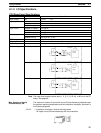
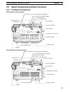
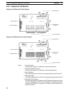
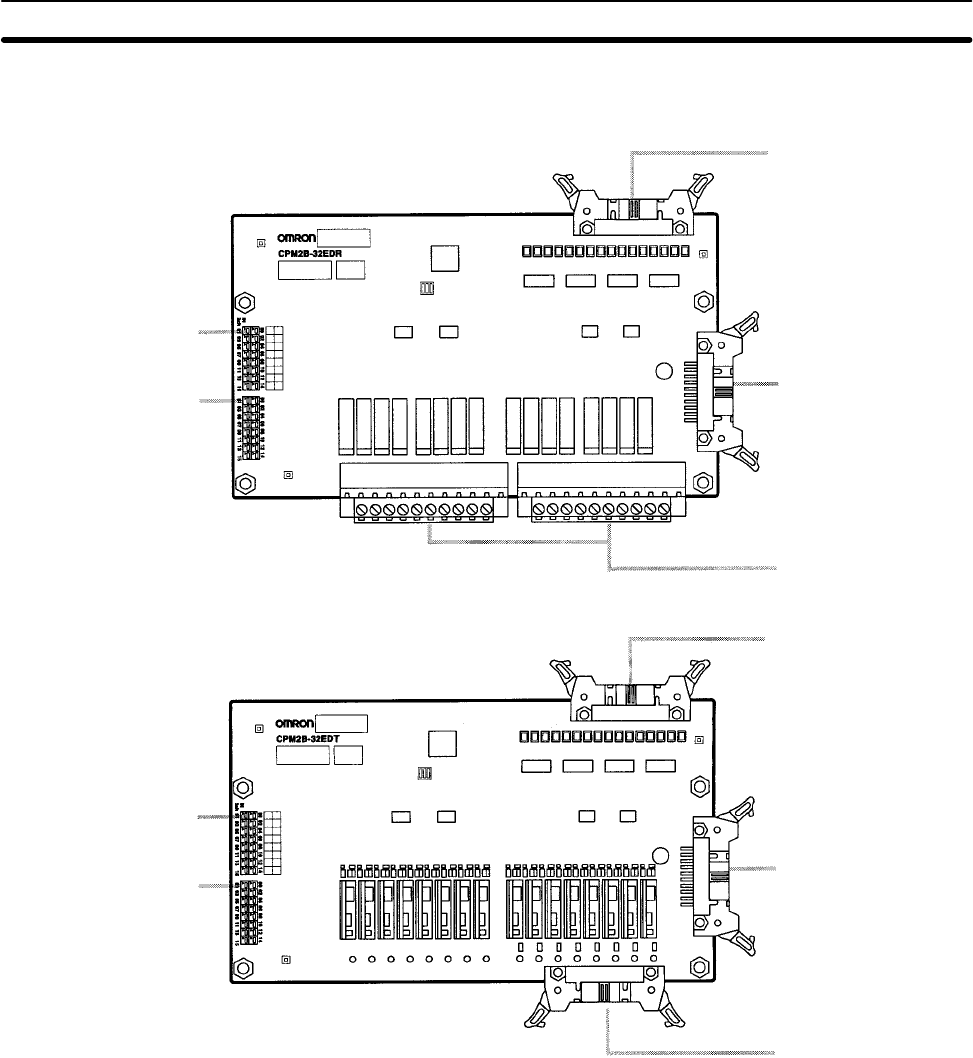
2-2-2 Expansion I/O Boards
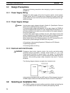
Expansion I/O Boards with Relay Outputs
3. Input indicators
4. Output indicators
5. Expansion I/O
connector
1. Input connector
2. Output terminals
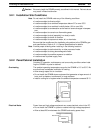
Expansion I/O Boards with Transistor Outputs
2. Output connector
3. Input indicators
4. Output indicators
5. Expansion I/O
connector
1. Input connector
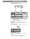
1, 2, 3... 1. Input Connector
Connects the Expansion I/O Board to external input devices.
2. Output Terminals/Connector
Connects the Expansion I/O Board to external output devices.
3. Input Indicators
The input indicators are lit when the corresponding input terminal is ON.
4. Output Indicators
The output indicators are lit when the corresponding output terminal is ON.
5. Expansion I/O Connector
Connects the Expansion I/O Board to the CPU Board or the previous Expan-
sion Unit or Expansion I/O Unit. Up to 3 Expansion I/O Boards can be con-
nected to a CPU Board. An Expansion I/O Cable is included with each Ex-
pansion I/O Board.