


6EC Directives
xvii
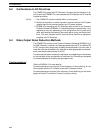
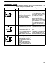
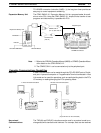
Countermeasure Examples
When switching an inductive load, connect a surge protector, diodes, etc., in par-
allel with the load or contact as shown below.
Circuit Current Characteristic Required element
AC DC
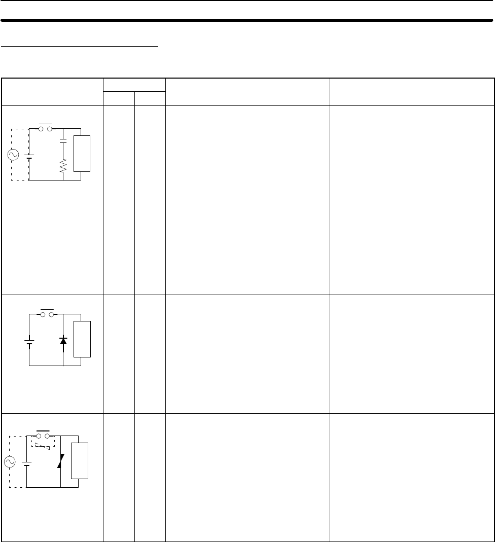
CR method
Power
supply
Inductive
load
Yes Yes If the load is a relay or solenoid, there
is a time lag between the moment the
circuit is opened and the moment the
load is reset.
If the supply voltage is 24 to 48 V,
insert the surge protector in parallel
with the load. If the supply voltage is
100 to 200 V, insert the surge
protector between the contacts.
The capacitance of the capacitor must
be 1 to 0.5 µF per contact current of
1 A and resistance of the resistor must
be 0.5 to 1 Ω per contact voltage of
1 V. These values, however, vary with
the load and the characteristics of the
relay. Decide these values from
experiments, and take into
consideration that the capacitance
suppresses spark discharge when the
contacts are separated and the
resistance limits the current that flows
into the load when the circuit is closed
again.
The dielectric strength of the capacitor
must be 200 to 300 V. If the circuit is
an AC circuit, use a capacitor with no
polarity.
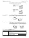
Diode method
Power
supply
Inductive
load
No Yes The diode connected in parallel with
the load changes energy accumulated
by the coil into a current, which then
flows into the coil so that the current
will be converted into Joule heat by
the resistance of the inductive load.
This time lag, between the moment
the circuit is opened and the moment
the load is reset, caused by this
method is longer than that caused by
the CR method.
The reversed dielectric strength value
of the diode must be at least 10 times
as large as the circuit voltage value.
The forward current of the diode must
be the same as or larger than the load
current.
The reversed dielectric strength value
of the diode may be two to three times
larger than the supply voltage if the
surge protector is applied to electronic
circuits with low circuit voltages.
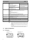
Varistor method
Power
supply
Inductive
load
Yes Yes The varistor method prevents the
imposition of high voltage between the
contacts by using the constant voltage
characteristic of the varistor. There is
time lag between the moment the
circuit is opened and the moment the
load is reset.
If the supply voltage is 24 to 48 V,
insert the varistor in parallel with the
load. If the supply voltage is 100 to
200 V, insert the varistor between the
contacts.
---