


4-3SectionSR Area
58
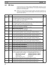
4-3 SR Area
These bits mainly serve as flags related to CPM2A/CPM2C operation or contain
present and set values for various functions. The functions of the SR area are
explained in the following table.
Note “Read-only” words and bits can be read as status in controller PC operation, but
they cannot be written from the ladder program. Bits and words that are “Not
used” are also read-only.
Word(s) Bit(s) Function Read/
write
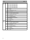
SR 228,
SR 229
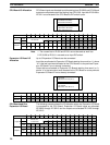
00 to 15 Pulse Output PV 0
Contains the pulse output PV (–16,777,215 to 16,777,215). SR 22915 acts as the sign
bit; a negative number is indicated when SR 22915 is ON.
(The same PV data can be read immediately with PRV(62).)
Only Pulse Output PV 0 is used for ACC(––).
Read-
only
SR 230,
SR 231
00 to 15 Pulse Output PV 1
Contains the pulse output PV (–16,777,215 to 16,777,215). SR 23115 acts as the sign
bit; a negative number is indicated when SR 23115 is ON.
(The same PV data can be read immediately with PRV(62).)
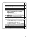
SR 232
to
SR 235
00 to 15 Macro Function Input Area
Contains the input operands for MCRO(99).
(Can be used as work bits when MCRO(99) is not used.)
Read/
write
SR 236
to
SR 239
00 to 15 Macro Function Output Area
Contains the output operands for MCRO(99).
(Can be used as work bits when MCRO(99) is not used.)
SR 240 00 to 15 Interrupt Input 00003 Counter Mode SV
SV when interrupt input 00003 is used in counter mode (4 digits hexadecimal).
(Can be used as work bits when interrupt input 00003 is not used in counter mode.)
SR 241 00 to 15 Interrupt Input 00004 Counter Mode SV
SV when interrupt input 00004 is used in counter mode (4 digits hexadecimal).
(Can be used as work bits when interrupt input 00004 is not used in counter mode.)
SR 242 00 to 15 Interrupt Input 00005 Counter Mode SV
SV when interrupt input 00005 is used in counter mode (4 digits hexadecimal).
(Can be used as work bits when interrupt input 00005 is not used in counter mode.)
SR 243 00 to 15 Interrupt Input 00006 Counter Mode SV
SV when interrupt input 00006 is used in counter mode (4 digits hexadecimal).
(Can be used as work bits when interrupt input 00006 is not used in counter mode.)
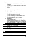
SR 244 00 to 15 Interrupt Input 00003 Counter Mode PV
Counter PV when interrupt input 00003 is used in counter mode (4 digits hexadecimal).
SR 245 00 to 15 Interrupt Input 00004 Counter Mode PV
Counter PV when interrupt input 00004 is used in counter mode (4 digits hexadecimal).
SR 246 00 to 15 Interrupt Input 00005 Counter Mode PV
Counter PV when interrupt input 00005 is used in counter mode (4 digits hexadecimal).
SR 247 00 to 15 Interrupt Input 00006 Counter Mode PV
Counter PV when interrupt input 00006 is used in counter mode (4 digits hexadecimal).
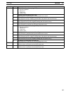
SR 248,
SR 249
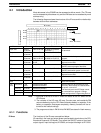
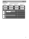
00 to 15 High-speed Counter PV Area
The PVs can have the following values. The leftmost digit of SR 249 acts as the sign
indicator; a negative number is indicated when the leftmost digit of SR 249 is F.
Differential phase input mode: –8,388,608 (F838 8608) to 8,388,607
Pulse +direction input mode: –8,388,608 (F838 8608) to 8,388,607
Up/down pulse input mode: –8,388,608 (F838 8608) to 8,388,607
Increment mode: 0 to 16,777,215
Synchronized pulse control: 0 to 20,000 Hz
(Can be used as work bits when the high-speed counter is not used.)
Read-
only
SR 250 00 to 15 Analog Setting 0
Used to store the 4-digit BCD set value (0000 to 0200) from analog control 0.
SR 251 00 to 15 Analog Setting 1
Used to store the 4-digit BCD set value (0000 to 0200) from analog control 1.