


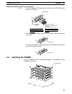
3-5SectionWiring and Connections
47
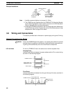
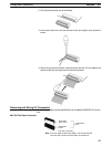
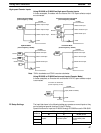
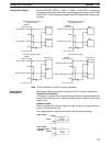
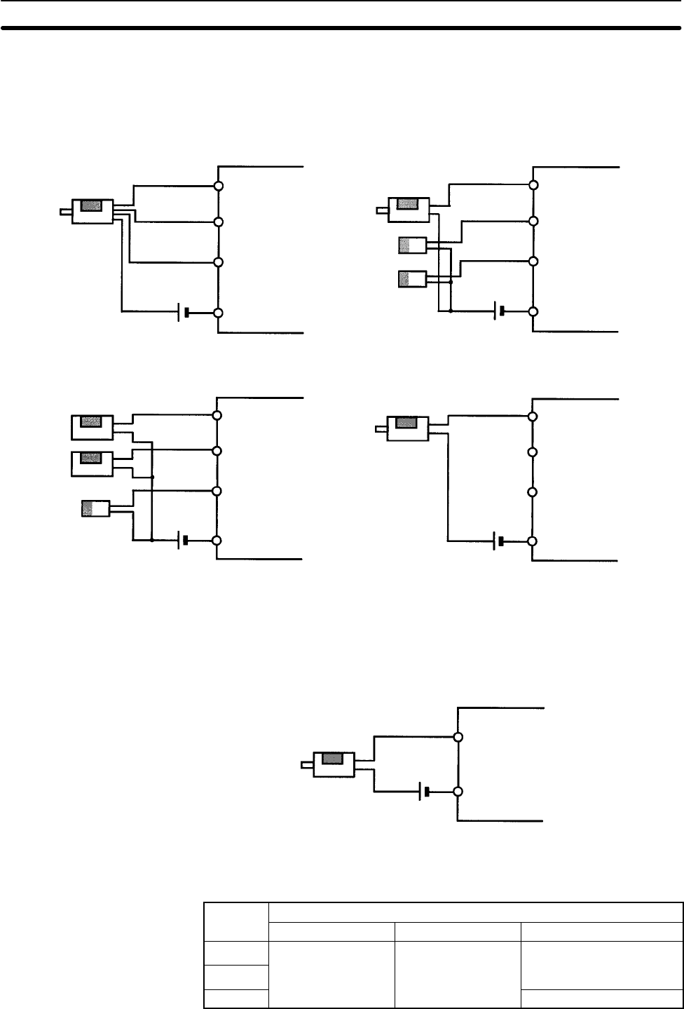
High-speed Counter Inputs
Using IR 00000 to IR 00002 as High-speed Counter Inputs
In these examples, Encoders with an external 24-V DC open-collector output
are connected.
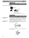
Differential Phase Mode
(Count frequency: 5 kHz)
Encoder
24 V DC
00000 A-phase input
00001 B-phase input
COM
00002 Z-phase input
Pulse Plus Direction Input Mode
(Count frequency: 20 kHz)
Encoder
24 V DC
00000 Pulse input
00001 Direction input
COM
00002 Reset input
Sensor or switch
CPM2B CPM2B
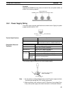
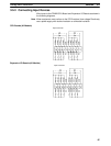
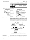
Up/Down Mode
(Count frequency: 20 kHz)
24 V DC
00000 CW input*
00001 CCW input*
COM
00002 Reset input
Increment Mode
(Count frequency: 20 kHz)
Encoder
24 V DC
00000 Pulse input
00001 Normal input
COM
00002 Normal input
CPM2B
CPM2B
Sensor
Sensor
Sensor or switch
Sensor or switch
Note *CW is clockwise and CCW is counter-clockwise.
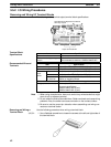
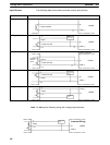
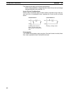
Using IR 00003 to IR 00006 as Interrupt Inputs (Counter Mode)
In these examples, an Encoder with an external 24-V DC open-collector output
is connected.
Increment or decrement
(Count frequency: 2 kHz)
Encoder
24 V DC
Input (00003 to 00006)
COM
CPM2B
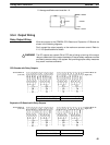
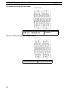
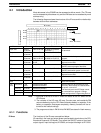
The input bits shown in the following tables can operate as normal inputs or they
can be assigned special functions in the PC Setup.
Special functions for input bits IR 00000 through IR 00002 are set in DM 6642:
Bit
PC Setup setting (DM 6642 bits 08 to15)
address
00 01 02, 03, or 04
IR 00000
Used as normal Used as high-speed Used as inputs for
IR 00001
inputs. counter inputs. synchronized pulse
control.
IR 00002 Used as a normal input.
PC Setup Settings