1-2SectionSystem Configurations
10
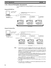
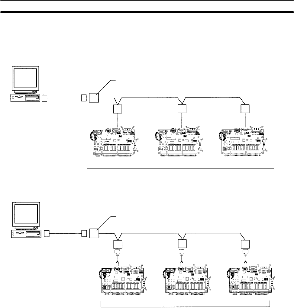
1-2-6 One-to-N Computer Connections
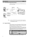
Up to 32 OMRON PCs, including CPM2B PCs, can be connected to a host com-
puter.
Using the RS-232C Port
RS-422 (Total length: 500 m max.)
NT-AL001-E
(See note 1.)
NT-AL001-E
(See note 1.)
NT-AL001-E
(See note 1.)
Up to 32 PCs
CPM2B CPU Board CPM2B CPU Board CPM2B CPU Board
3G2A9-AL004-E or NT-AL001-E (requires +5 V)
(See notes 1 and 2.)
Connecting Cable
XW2Z-j00S-V
IBM PC/AT or
compatible computer
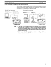
Using the Peripheral Port
RS-422 (Total length: 500 m max.)
CPM1-CIF11
(See note 3.)
Up to 32 PCs
CPM2B CPU Board CPM2B CPU Board
CPM2B CPU Board
3G2A9-AL004-E or NT-AL001-E (requires +5 V)
(See notes 1.)
Connecting Cable
XW2Z-j00S-V
CPM1-CIF11
(See note 3.)
CPM1-CIF11
(See note 3.)
CS1W-CN114
CS1W-CN114
CS1W-CN114
IBM PC/AT or
compatible computer
Note 1. The NT-AL001-E must be supplied externally with 5 V DC. When an NT-
AL001-E is connected to a CPM2B PC, pin 6 of the CPM2B’s RS-232C port
supplies +5 V DC and an external power supply is not necessary. When the
NT-AL001-E is connected to a host computer, it is necessary to supply 5 V
DC from an external power supply.
If an NT-AL001-E is connected to the CPM2B’s RS-232C port, only one Ex-
pansion I/O Board can be connected to the CPU Board because the NT-
AL001-E draws its 5-V DC power from the CPU Board.
Use an XW2Z-070T-1 (0.7 m) or XW2Z-200T-1 (2 m) cable to connect the
NT-AL001-E to the CPM2B’s RS-232C port.
2. The 3G2A9-AL004-E requires an external AC power supply (110 V AC or
220 V AC).
3. The CPM1-CIF11 is supplied +5 V DC from the peripheral port so an exter-
nal power supply is not necessary.


