


!
3-5SectionWiring and Connections
49
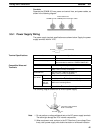
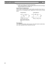
2. Average rectified current must be 1 A.
IN
COM
CPM2B
Diode
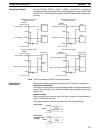
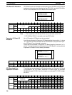
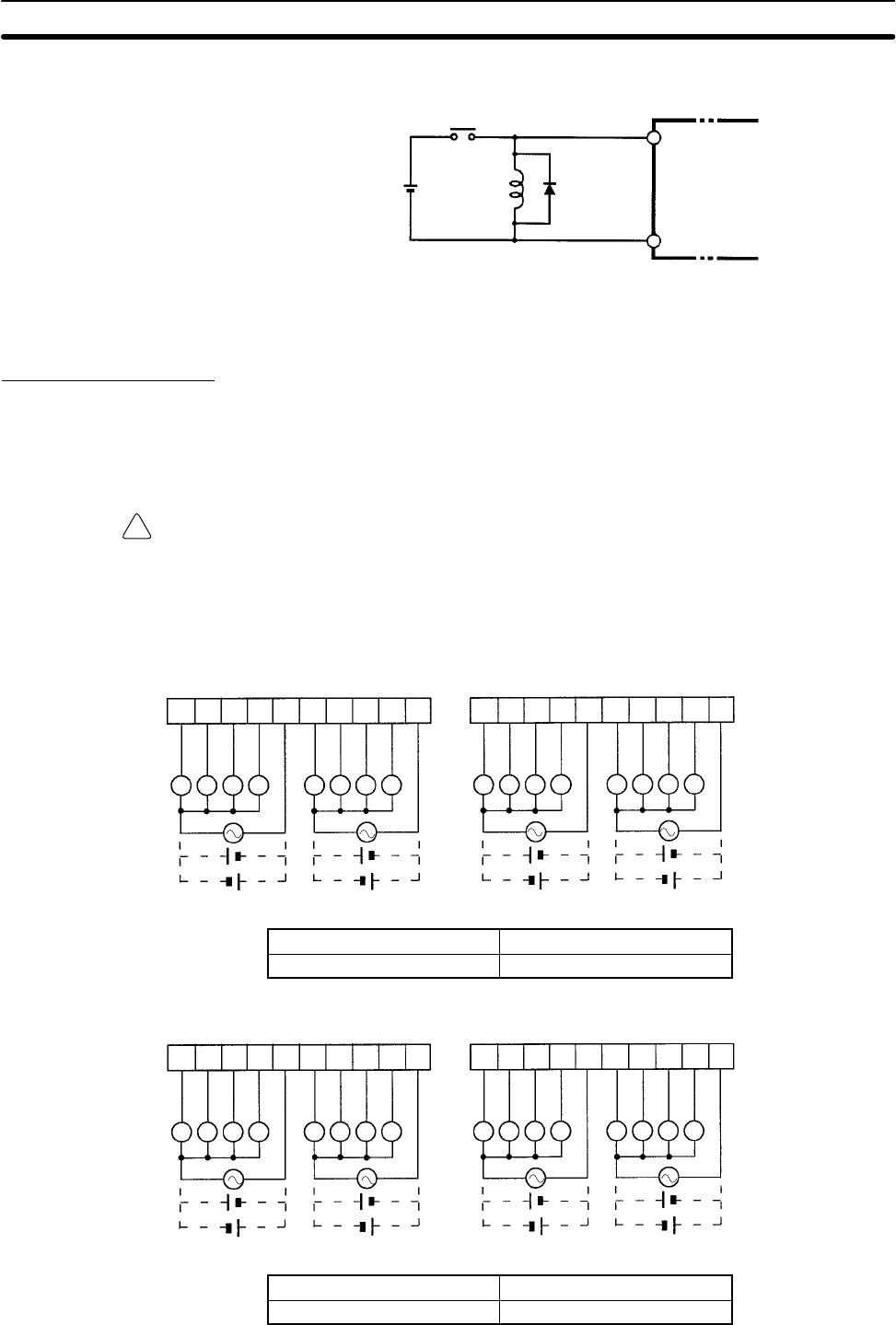
3-5-4 Output Wiring
Relay Output Wiring
Wire the outputs to the CPM2B’s CPU Board and Expansion I/O Boards as
shown in the following diagrams.
Don’t exceed the output capacity or the maximum common current. Refer to
2-1-3 I/O Specifications for details.
WARNING The PC outputs may remain ON or OFF due to fusing or burning of the output
relays or destruction of the output transistors. External safety measures must be
provided to ensure safety in the system. Not providing proper safety measures
may result in serious accidents.
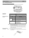
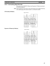
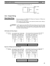
CPU Boards with Relay Outputs
Terminal Block #1
(Left side)
Terminal Block #2
(Right side)
12345678910 12345678910
LLLL LLLL LLLL LLLL
01005
01006
01007
01000
COM
01001
01002
01003
01004
COM
01105
01106
01107
01100
COM
01101
01102
01103
01104
COM
Output capacity Max. common capacity
2 A (250 V AC or 24 V DC) 4 A/common
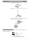
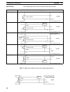
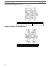
Expansion I/O Boards with Relay Outputs
Terminal Block #1
(Left side)
Terminal Block #2
(Right side)
LLLL LLLL LLLL LLLL
01 00
COM
COM
j
01 01
j
01 02
j
01 03
j
01 04
j
01 05
j
01 06
j
01 07
j
12345678910 12345678910
01 08
COM
COM
j
01 09
j
01 10
j
01 11
j
01 12
j
01 13
j
01 14
j
01 15
j
Output capacity Max. common capacity
2 A (250 V AC or 24 V DC) 4 A/common