


!
3-5SectionWiring and Connections
40
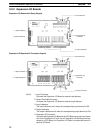
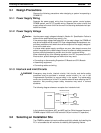
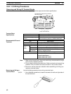
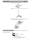
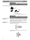
Example Installations
Mounting Bracket
Screw and nut
installation
Screw and tapped
panel installation
Note 1. Use M4 screws and tighten to a torque of 1.2 NSm.
2. The CPM2B can be installed without a CPM2B-ATT01 Mounting Bracket,
but the Mounting Bracket must be used to conform to UL/CSA standards.
Refer to Appendix B for mounting dimensions.
3. Installing the CPM2B horizontally or with its narrow edge down affects cool-
ing and limits the number of inputs that can be ON simultaneously at high
temperatures. Refer to page 26 for details.
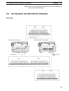
3-5 Wiring and Connections
This section provides basic information on power supply wiring and I/O wiring.
General Precautions for Wiring
Caution Cover the CPM2B Boards with plastic or use some other method to prevent
strands of wire from getting on the Board or inside the Board’s components dur-
ing wiring. Wire strands may short circuit the Board’s components.
Do not run CPM2B I/O lines in the same duct or conduit as power lines.
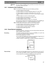
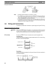
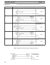
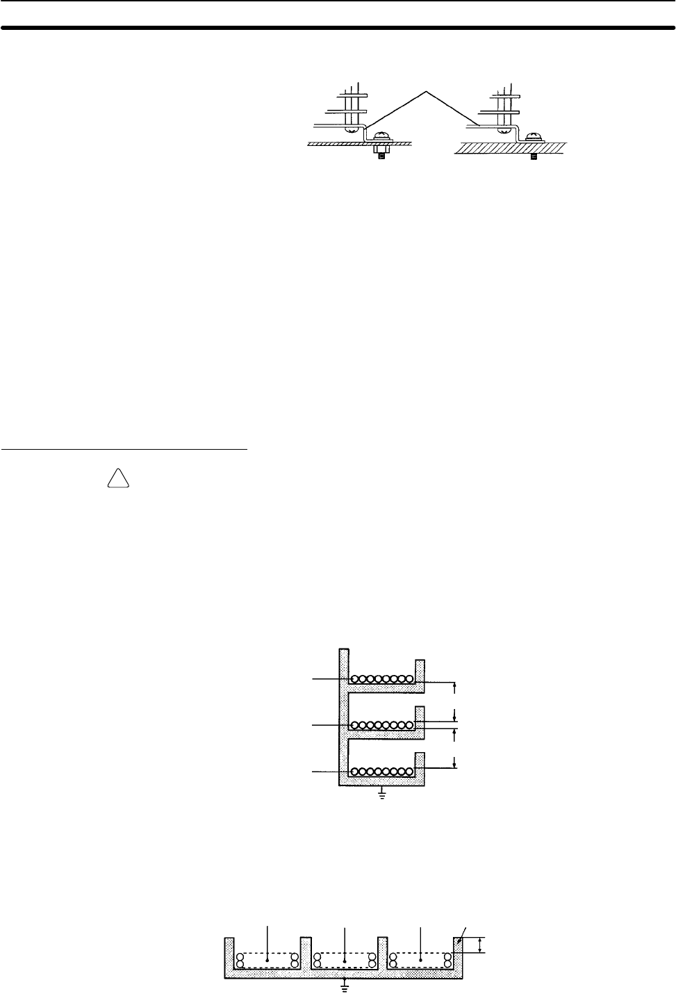
Hanging Ducts
Leave at least 300 mm between the power cables and the I/O or control wiring,
as shown in the following diagram.
CPM2B I/O lines
Control cables and
CPM2B power lines
Power cables
300 mm min.
300 mm min.
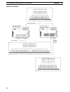
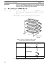
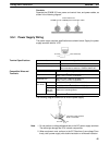
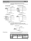
Floor Ducts
Leave at least 200 mm between the wiring and the top of the duct, as shown in
the following diagram.
200 mm min.
Metal plate (iron)
CPM2B I/O lines
Control cables and
CPM2B power lines
Power cables
I/O Line Noise