


3-5SectionWiring and Connections
51
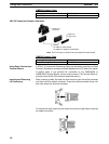
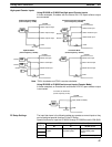
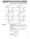
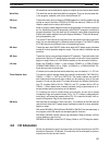
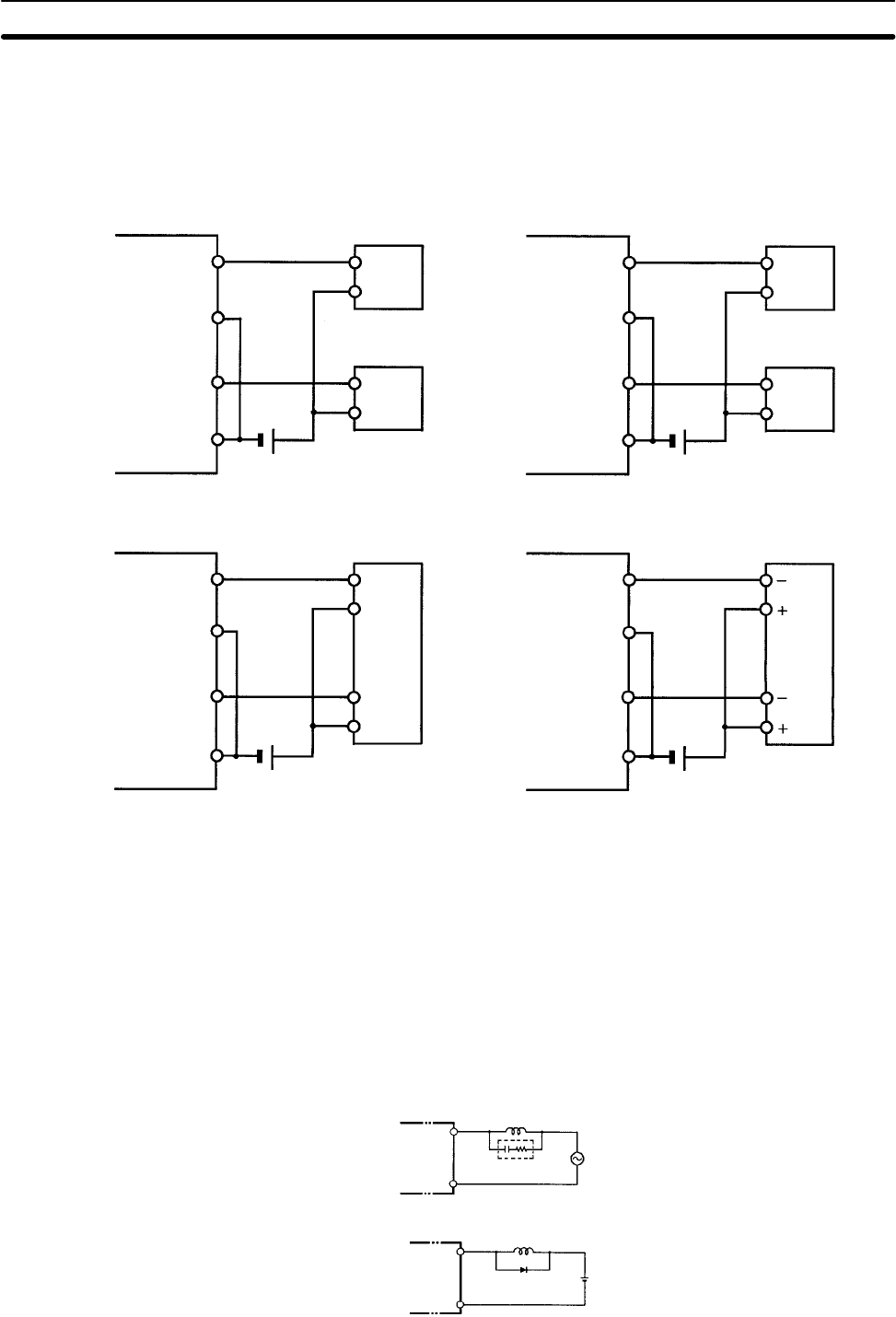
Use the PULS(65), SPED(––), ACC(––), PWM(––), and SYNC(––) instructions
to produce pulse outputs (rather than normal outputs) from output bits IR 01000
and IR 01001. Pulse outputs are possible from CPU Boards with transistor out-
puts only.
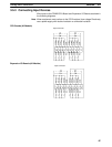
CPM2B
Single-phase pulse output
(Fixed duty ratio)
Motor driver
Pulse output 0: 01000
CPM2B
Pulse output 1: 01001
COM
Motor driver
Single-phase pulse output
(Variable duty ratio)
Relay
Pulse output 0: 01000
CPM2B
Pulse output 1: 01001
COM
Relay
Pulse plus direction output
Motor driver
Pulse output 0: 01000
CPM2B
Direction output: 01001
COM
Direction
input
Increment pulse output
Motor driver
CW* pulse output: 01000
CCW* pulse output: 01001
COM
CW input
CCW input
COM
COM
COM
COM
Note *CW is clockwise and CCW is counter-clockwise.
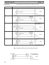
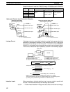
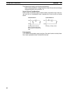
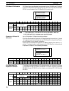
Observe the following precautions to protect the PC’s internal components.
Output Short Protection
The output or internal circuitry might be damaged when the load connected to an
output is short-circuited, so it is recommended to install a protective fuse in each
output circuit.
Inductive Loads
When connecting an inductive load to an input, connect a surge protector or
diode in parallel with the load.
The surge protector’s components should have the following ratings:
OUT
COM
CPM2B
Surge protector
Relay Output
OUT
COM
CPM2B
Diode
Relay Output
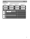
Transistor Output
(Sinking)
Using Pulse Outputs
Output Wiring
Precautions