3-3SectionAssembling the CPM2B Boards
38
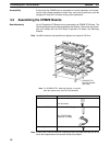
Ensure that the CPM2B can be accessed for normal operation and mainte-
nance. High-voltage equipment, power lines, and moving machinery could be
dangerous if they are in the way during routine operations.
3-3 Assembling the CPM2B Boards
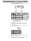
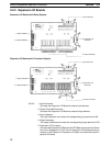
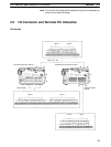
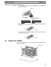
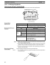
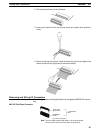
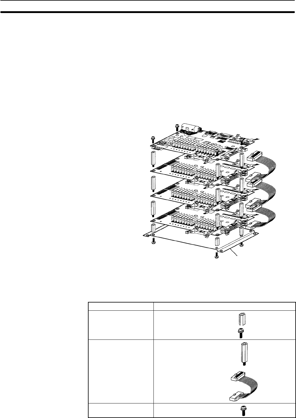
Up to 3 Expansion I/O Boards can be connected to a CPM2B CPU Board. The
following diagram shows how to assemble the Boards. The screws and stand-
offs are included with the CPU Board, Expansion I/O Board, and Mounting
Bracket.
Note Use M3 screws for the standoffs and tighten to a torque of 0.5 NSm.
Note The CPM2B-ATT01 Mounting Bracket is required
when the system must meet UL/CSA standards.
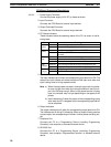
CPM2B-ATT01
Mounting Bracket
(See note.)
Board or Bracket
Hardware and cables included
CPU Board Four M3 standoffs (short)
Four M3 screws
Expansion I/O Board
Four M3 standoffs (long)
One CPM2B-CN601
Expansion I/O Cable
Mounting Bracket Four M3 screws
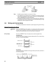
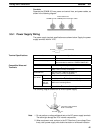
Note Some of the CPM2B’s electrical components such as leads are sharp, so do not
touch the components or the surface of the circuit board.
Accessibility
Board Assembly


