


5
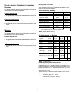
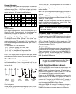
Keypad Addressing
The S5832SG control panel will support up to 16 hardwired
keypads. Each keypad must have a different address, with
addresses ranging from 1 - 16. (Figure 6 shows the location
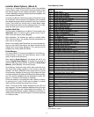
of the switch used to address the keypad.) Table 5 lists the
switch settings for S1 for each keypad address.
Addr A0 A1 A2 A3
1 on off off off
2 off on off off
3 on on off off
4 off off on off
5 on off on off
6 off on on off
7 on on on off
8 off off off on
Addr A0 A1 A2 A3
9 on off off on
10 off on off on
11 on on off on
12 off off on on
13 on off on on
14 off on on on
15 on on on on
16 off off off off
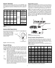
Each keypad (Alphanumeric, Icon, or LED) may draw up to
50 mA of current. Once connected, the control panel will
automatically recognize the presence of the keypad.
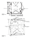
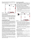
Zone Terminals
The basic configuration of the S5832SG can support up
to 8 hardwired zones. Zone 8 is a powered loop for use
with two-wire smoke detectors. This loop is current-lim-
ited at 30 mA.
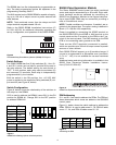
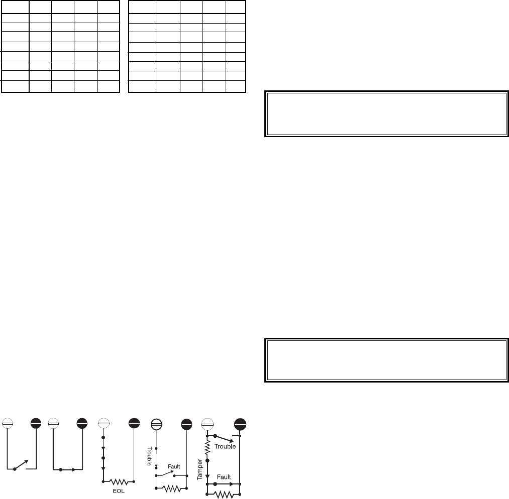
a) N.O.
Normally
Open
b) N.C.
Normally
Closed
c) EOL
End-of-Line
Resistor
d) EOL,
Supervised
e) 2x EOL
4-state
supervision
Figure 7
Zone Configurations
Table 5
Keypad Addressing
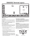
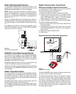
Connecting an Auxiliary Keypad (J8)
The S5832SG Control Panel also has a 4-pin Molex
®
con-
nector (J8) for attaching an auxiliary keypad to the panel for
on-site programming. The connector (J8) is located on the
PCB above the Keypad Data Bus terminals (see Figure 6,
on page 4).
The connections to J8 are as follows:
Pin 1 Common (ground) for Power return.
Pin 2 Supplies +12 VDC to power the keypad.
Pin 3 KY+ on the differential keypad data bus.
Pin 4 KY on the differential keypad data bus.
Pins 1 and 2 supply power and ground, while pins 3 and 4
provide communication between the panel and the keypad.
S5050 Relay/Event Memory Module
The Sierra S5832SG control panel will support up to two
Model S5050 REMMs connected to the keypad data bus.
NOTE: Trouble conditions and tampers, if enabled, are re-
ported via the keypad bus. Refer to Block 4, CL 158 and
159, respectively, for report routing information.
Power for the S5050 REMM is obtained by connecting the
KPWR terminal on the REMM PCB to either the KPWR or
AUX terminal on the control panel. For the power return,
connect the C terminal on the REMM to the C terminal on
the control panel. The GND terminal on the REMM PCB is
used to connect the REMM to Earth Ground.
Adding one REMM will increase Event Memory storage ca-
pability from 60 events to 250 events. Adding a second
REMM will increase the storage capacity to 500 events.
Caution: When connecting accessories to the system,
use care not to exceed rated outputs. (See Table 1
on page 3 for Accessory loading information.)
Accessories
The Sierra S5832SG supports a variety of accessories which
communicate with the panel through the keypad data bus.
These accessories can include up to two Model S5050 Re-
lay/Event Memory Modules (REMM), up to three Model
S5058 Zone Expansion Modules (ZEM), and a Model SN915-
BUS SpreadNet
®
RF Receiver.
On-Board Relay Terminals (TB2)
The Sierra S5832EB has a single-pole, double-throw (Form
C) relay mounted on the PCB. Connections to the relay are
made at TB2. (Refer to Figure 1 for relay terminal location.)
The on-board relay may be configured as Normally Open
(N.O.) or Normally Closed (N.C.) and can switch up to 1 A of
current at 12 VDC. For programming options, refer to Block 7,
Command Location (CL) 001.
Zones may be configured with Normally Open (N.O.) or Nor-
mally Closed (N.C.) contacts (although not recommended).
NOTE: For devices requiring a 10K Ohm EOL resistor,
use Zone 7 and remove jumper J5. (See page 1, Figure
1 for jumper location.)
The N.O. and N.C. zone configurations do not provide for
supervision of the detection devices.
The following configurations provide supervision of the de-
tection devices:
EOL: This zone configuration uses a single EOL resistor to
detect the following conditions: Normal (2.2K), Fault (open
or short).
Supervised EOL: This zone configuration uses a single EOL
resistor to detect the following conditions: Normal (2.2K), Fault
(short), or Trouble (open).
Tamper: This zone configuration uses two EOL resistors to
detect four different zone conditions: Normal (2.2K), Fault
(4.4K), Trouble (short), or Tamper (open).